Link an AutoCAD Electrical toolset project to an Inventor project for data exchange and interoperability.
- Associate a 2D schematic representation to a 3D model
- Synchronize project design data in real-time
- View physical properties such as wire lengths in AutoCAD Electrical toolset that helps you estimate actual wire length
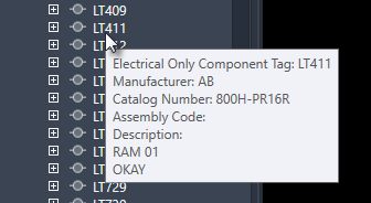
- View attributes defined by mechanical users and compare them with electrical attributes defined in AutoCAD Electrical toolset, which helps you to align component properties on logical and physical side
- Export component, wiring, and connection details to Microsoft® Excel format for quick reports
- Automatically route the wires and cables in Inventor based on the connections defined in AutoCAD Electrical toolset
- Location View tab on Project Manager in AutoCAD Electrical toolset
- Location View in Inventor
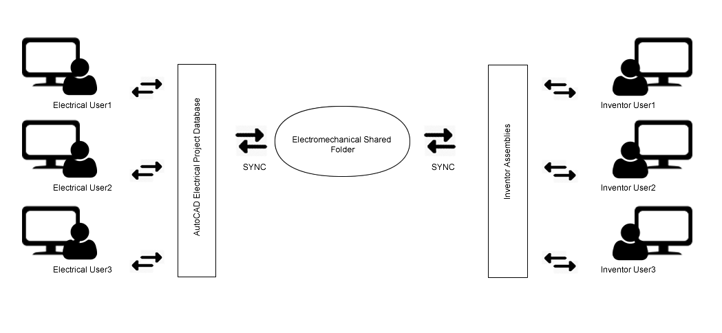
Synchronization
Electromechanical project manages and maintains data integrity between AutoCAD Electrical toolset and Inventor projects through synchronization. Synchronization, in electromechanical project, uses a push and pull approach during the process of data exchange. In case of AutoCAD Electrical toolset users; the Inventor data is first pulled in and your component tree view is updated, and then AutoCAD Electrical toolset data is pushed out to Inventor. Synchronization fails when you are disconnected from the network and the connection to the link file is broken—you can continue to work offline on your drawing files and use the location view tab to manage the components. You can synchronize your offline work after you have re-established the connection to the link file in the network.
Reuse
When working in a collaborative and connected environment, it is a common practice to reuse existing projects. You can reuse your electromechanical linked project by doing a Copy Project operation—create a new electromechanical link file for your copied project or correct the data in your copied electromechanical link file.
Component Tree
Displays a list of standard components, terminals, PLC modules, connectors, and cable markers. The top node in the tree represents the entire project. Each node under the project represents an Installation value. The nodes under each Installation represent the Location values within that Installation.
The various device types are represented differently in the component tree. When inserting electrical components, it is recommended that you should have unique names (installation code, location code, and component tag), pins, and terminals numbers. For example, if you have cable markers in your drawing, which has duplicate values for cable tag, then you may experience unexpected behaviour of the component in the component tree view and in the connections tab. This is more commonly observed for terminals and cable markers in Location View.
- Standard Component
-
 Tag value. Expand to view assigned pins.

- Terminal
-
Tagstrip value: terminal number. A multi-level terminal lists each terminal number separated by a comma. Expand to view the level descriptions.
 Note: Terminals that take on the wire number show the wire number in place of a terminal number.
 - PLC
-
Tag value. Expand to view each pin and address value.

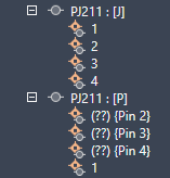
- Connector
-
Tag value separated into two rows, one for the plug side and one for the jack side. Expand to view the pins.
- Cable
-
 Tag value.

- Child
- A child component is excluded from the tree until the parent is inserted.