Once you have finalized the model and generated a preview image, you define the insertion behaviors. These include the trim lengths and placement point used by the software during autolayout. Trim lengths define the distance that a connecting segment is trimmed in order for the fitting to be placed in the run.
- In the part browser, click
 .
. The Options dialog box is displayed.
- Select or clear Custom Sizing Flag and Hide Part Flag, as appropriate.
For descriptions of these settings, see Part Insertion Behaviors of a Parametric Part.
- Select Auto Layout Flag to turn on auto layout, and click OK.
In the part browser, Autolayout Data is added to the Modeling folder, and trim length points are displayed on the model in the modeling area.
- Change the model view to plan view by clicking
 .
.
The command line issues the next command.
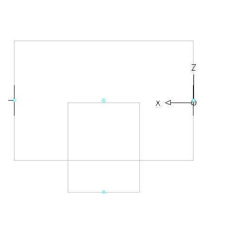
- In the part browser, expand Autolayout Data, right-click Layout Data and click Add Trim Length. Note: To ensure components are trimmed correctly when placing a parametric part into a drawing, you must define trim lengths for the part in a specific order—left to right, then bottom to top.
You are prompted to select the start and end of the trim length. Repeat this for the 3 trim lengths required for auto layout of the tee fitting.

- Define the first trim length.
For the start of trim length 1, select the point at the center of the trunk. For the end of trim length 1, select the point at the left end of the trunk.
- Define the second trim length.
For the start of trim length 2, select the point at the center of the trunk. For the end of trim length 2, select the point at the right end of the trunk.
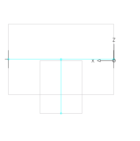
- Define the third trim length.
For the start of trim length 3, select the point at the top of the branch (the center of the trunk). For the end of trim length 3, select the point at the bottom of the branch.
Trim length lines are displayed between the selected points.
- Define the first trim length.
- In the part browser, right-click Layout Data, and click Select Placement Point.
You are prompted to select a point on your model. This point is the location at which connecting segments would intersect if they were extended along their logical paths. The placement point is used as the insertion point for the fitting when it is added to a drawing during autolayout using the Add commands.
- Select the trim length point at the center of the trunk.
A placement point is displayed at the selected location.
