When you select the drafting standard (and the revision), the default settings for welding symbols change to match that drafting standard. If necessary, you can customize these settings to suit your drafting requirements
Because text and leader lines are the most common objects used for annotations, AutoCAD Mechanical toolset provides a single configuration point (the Standard Settings dialog box) enabling you specify their default properties. These settings are the master settings.
In the Welding Settings dialog box, the text and leader settings default to “By NameOfCurrentDraftingStandard.” If you modify the master settings, welding symbols automatically acquire the new settings. If you do not want welding symbols to follow the master settings, you can override the text height and select a specific value.
- Weld type symbols.
- Contour symbols.
- Stagger symbols (ISO and ISO based standards only).
- Peripheral symbol (GB standard only).
- Field weld symbol.
- All around symbol.
- Tail symbol.
- Length of reference and identification lines.
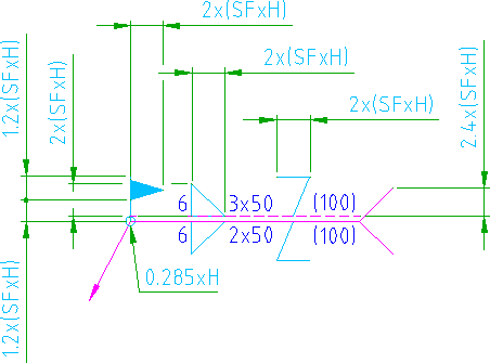
In order to control the size of these elements (excluding the reference and identification lines and the all around symbol) you can change the scale factor property of the welding symbol. The illustration shown below is an ISO welding symbol. The heights of the various elements that depend on the text height are shown as a formula, where H is the text height and SF is the scale factor. The formula changes from drafting standard to drafting standard.
You can also specify which weld type symbols are available for selection when you insert a welding symbol into a drawing. You can also configure the gap between the identification line and reference line, as well as the gap between the first and second processes.