In this exercise you create and work with REM enhanced bitonal region objects.
You can define an enhanced bitonal region by drawing a selection rectangle, polygon, or polyline (fence). From this selection figure, you can select raster entities within the figure, crossing the figure, or connected to such entities.
After you define the enhanced bitonal region object, you can modify the object using AutoCAD commands and REM commands.
In this exercise, you move raster entities in an image of a drill jig drawing. You also practice creating different types of enhanced bitonal region objects to better understand the various rules AutoCAD Raster Design toolset uses to construct such objects.
Related Exercises
Before doing this exercise, ensure that AutoCAD Raster Design toolset options are set as described in the exercise Exercise A1: Setting AutoCAD Raster Design Toolset Options.
Exercise
Separate the title block and schedule from the border
- In the \Tutorial3 folder, open the drawing file REM_03.dwg.
- Right-click on an open toolbar and open the REM Enhanced Bitonal Regions toolbar and the Raster Entity Manipulation Toolbar.
- Click
View menu
 Named Views. Set the current view to
TU_assembled_jig.
- Click Knife
 on the
Raster Entity Manipulation Toolbar.
In the next few steps you will use this tool to separate the title block and schedule from the border of this drawing.
- Just above the title block and schedule, select a start point inside the border, and an end point outside the border. These two points define a knife cut across the border.
The crosshairs show where to draw the first knife cut.
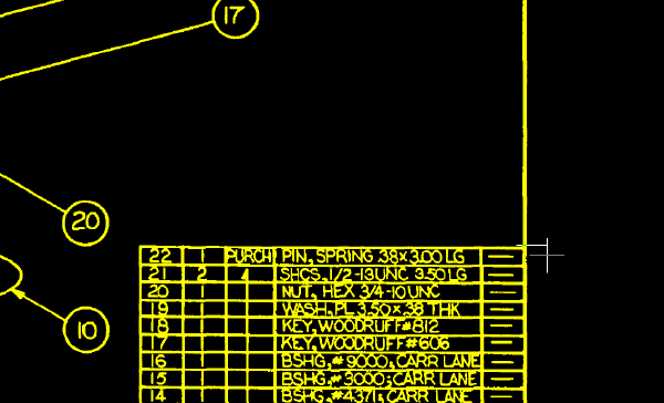
- On the lower left of the title block and schedule, define a vertical knife cut across the border, then press
Enter to end the command.
The crosshairs show where to draw the second knife cut.
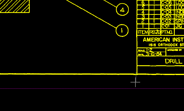
Remove the border from the drawing
- Click
View menu
 Named Views. Set the current view to
TU_assembled_jig.
- Click Smart Fence
 on the
REM Enhanced Bitonal Regions toolbar.
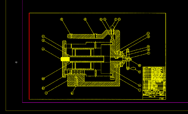
- Draw the fence across the left vertical line of the border and press
Enter.
The vertical line becomes a REM object.
Using a smart fence selects all raster primitives (lines, circles, and arcs) that touch the fence. In this example, only one line touches the fence.
- Right-click and click
REM
 Clear All.
The vertical line is no longer selected as a REM object.
- Click Connected Fence
 on the
REM Enhanced Bitonal Regions toolbar.
- Draw the fence across the left vertical line of the border and press
Enter.
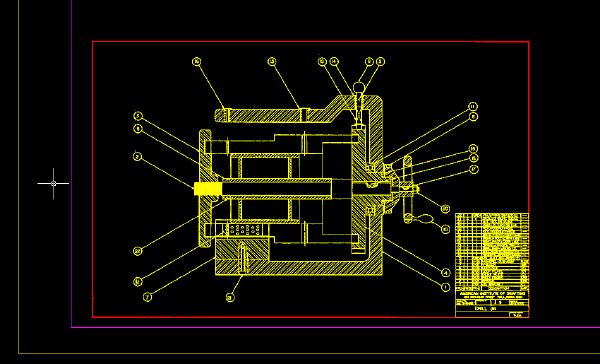
The whole border becomes a REM object.
Using a connected fence selects all raster entities connected to the raster entities that touch the fence. The border becomes a REM object when you use a connected fence to select the vertical line because the vertical and horizontal lines that make up the border are connected.
The title block and schedule, which you separated from the border using the Knife command, are not included in REM object.
- Select the border and enter
e (ERASE) to remove it, leaving the title block and schedule in place.
Move the title block and schedule
- Click Smart Window
 on the
REM Enhanced Bitonal Regions toolbar.
- Draw a window around the title block and schedule.
The title block and schedule become a REM object.
- Use the MOVE command to move the title block and schedule up and to the right of the assembly.
- Select the REM object, right-click, and click
Merge to Raster Image.
AutoCAD Raster Design toolset merges the REM object into the image. The title block and schedule are no longer a REM object.
Define REM objects using smart and connected windows
- Click
View menu
 Named Views. Set the current view to
TU_mandrel_rib_plate.
- Click Smart Window
 on the
REM Enhanced Bitonal Regions toolbar.
- Draw a window around the vertical leader line and the dimension text.
The following example shows where to draw the window around the leader line and the dimension text.
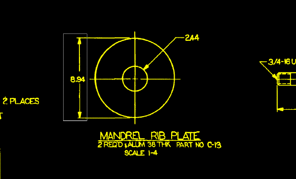
Using a smart window selects only the raster entities that are completely within the window: the vertical leader line and dimension text.
The horizontal dimension lines that cross the window are not selected.
- Right-click and click
REM
 Clear All from the shortcut menu. The raster entities are deselected.
- Click Connected Window
 on the
REM Enhanced Bitonal Regions toolbar.
- Draw a window around the same vertical leader line and the dimension text.
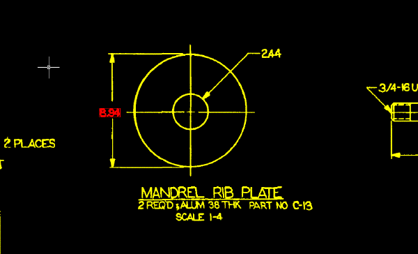
Using a connected window selects only the raster entities that are completely within the window and not connected to entities outside the window. In the following example, the leader lines are not selected because they are connected to the dimension lines, which extend outside the window.
- Right-click and click
REM
 Clear All from the shortcut menu. The entities are deselected.
Define REM objects using crossing windows
- Select Smart Crossing
 on the
REM Enhanced Bitonal Regions toolbar.
- Draw a crossing window around the same vertical leader line and dimension text.
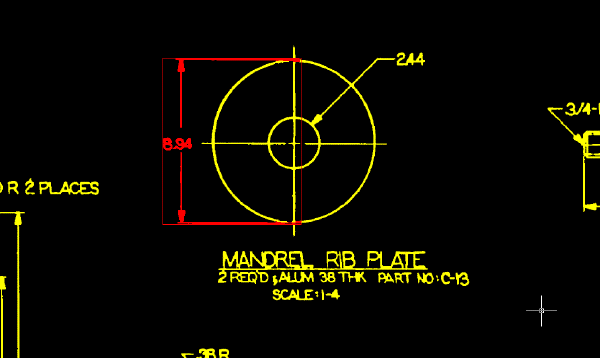
Using a smart crossing window selects all raster entities inside the window or crossing the window:
- The vertical leader line
- The dimension text
- The horizontal dimension lines
- Right-click and click
REM
 Clear All.
- Click Connected Crossing
 on the
REM Enhanced Bitonal Regions toolbar.
- Draw a crossing window around the vertical leader line and the dimension text.
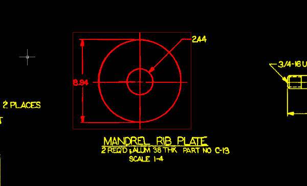
Using a connected crossing window selects all raster entities that are within the window, crossing the window, or connected to entities that cross the window.
In the following example, only the dimension text to the right of the part is not selected, because it is the only entity not connected to entities that cross the selection window.
- Right-click and click
REM
 Clear All from the shortcut menu.
- Close the drawing without saving changes.