In this exercise you learn how to modify the colors in an existing scanned USGS map.
First, you remove the green vegetation feature from the map in order to make the map more printer friendly and to allow other features to show more clearly. You can accomplish this by changing the green color in the map to the white background color. Next, you change the purple revisions to black in order to have them blend in with the rest of the map. Apply the same principle to highlight features in the map by changing them to a contrasting color. Finally, you isolate the contours by changing all other colors to the white background color.
This prepares the map for a contour-following operation.
Related Exercises
Before doing this exercise, you should ensure that AutoCAD Raster Design toolset options are set as described in the exercise Exercise A1: Setting AutoCAD Raster Design Toolset Options.
Exercise
- In the
..\Program Files\Autodesk\ApplicationPlugins\RasterDesign2022.Bundle\Contents\Tutorials\Tutorial7 folder, open the drawing file
Palette Manager01.dwg. The USGS topographic map image inserts with the drawing.
Eliminate vegetation features from the map
- To display the
Palette Manager dialog box, click
Image
 Image Processing
 Palette Manager.
Change green features to white
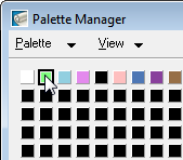
- Click the green button in the color table, (Index 1). The color and index are highlighted in the list view.

- When you select a color button, the Change button is available. Click Change to display the Target Color dialog box. The Target Color dialog box defaults to the last color picked, which in this exercise is green.
- Click the white button in the color table (Index 0). White is the background color of the map and by changing the green portion to white, the green is eliminated. Notice that details of the current selection are shown in the status bar just below the color buttons.

- Click OK to return to the Palette Manager dialog box. The green button has changed to white, reflecting the change you just made.
- If necessary, move the
Palette Manager dialog box aside to see the green area of the map, then click
Apply. The green vegetation feature is removed from the map.
Consolidate revisions by combining colors
Next, you change the purple map revisions to black in order to give the image a more uniform appearance. The purple revisions represent two different shades so it is possible to use either Change or Combine to consolidate them. In this part of the exercise you use Combine, which changes the index values in the image file.
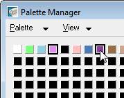
- Click light purple (index 3), then press the
Ctrl key and click dark purple (index 7).

- When you select more than one color, the
Combine button becomes available. Click
Combine. In the
Target Color dialog box, click black (index 4).

- Click
OK on the
Target Color dialog box, then click
OK on the
Palette Manager dialog box. The revision features that were purple are now black.
Isolate the contour information
One common use for scanned USGS topographical maps is to extract the contour information to vector so it can be used for terrain modeling. Using the Palette Manager, we can isolate the brown contour lines by changing the color of all other features to the background color. Once this is accomplished, we can convert the image to bitonal and use the VContour tool to convert the raster contours to vector.
One common use for scanned USGS topographical maps is to extract the contour information to vector so it can be used for terrain modeling. Using the Palette Manager, we can isolate the brown contour lines by changing the color of all other features to the background color.
- To open the
Palette Manager dialog box, click
Image
 Image Processing
 Palette Manager.
- Select the two shades of brown (indices 8 & 9) to start the isolation process. Since they are right next to each other you can window them for selection.

- With the cursor within the color table, right-click and click Invert Selection. All the color buttons with the exception of the two brown buttons are selected.
- Click Combine to display the Target Color dialog box. Click the white button (index 0) for the target color and click OK.
- Click OK in the Palette Manager dialog box. The result is an image that shows only contours.
- After inspecting the results, close the drawing without saving changes.