In this exercise, you review REM settings, define REM region objects, and copy raster entities from one image to another.
You can define region objects in bitonal, grayscale, and color images.
In this exercise, you work in a drawing that contains two bitonal images scanned from mechanical drawings:
- A detail drawing of a drill jig
- An assembly drawing of the same drill jig
You use REM commands to select entities in each image and then copy the entities to an empty image that is already in the drawing. In later exercises, you modify these entities using REM commands.
Related Exercises
Before doing this exercise, ensure that AutoCAD Raster Design toolset options are set as described in the exercise Exercise A1: Setting AutoCAD Raster Design Toolset Options.
Exercise
- In the
..\Program Files\Autodesk\ApplicationPlugins\RasterDesign2022.Bundle\Contents\Tutorials\Tutorial3 folder, open the drawing
REM_02.dwg.
Review the REM Settings
- To display the
Raster Design Options dialog box, click
Raster
 Options.
- Click the REM tab and ensure that the color of REM Objects is red.
- Click the
Raster Entity Detection tab and ensure the following settings are in effect:
- Max Jump Length is 10.
- Use Raster Pick Gravity is selected.
- Pick Aperture is 4.
- Float Tolerance is 2.
- Click OK.
- Right-click the AutoCAD toolbar or any open AutoCAD Raster Design toolset toolbar and click the Raster Entity Manipulation Toolbar to open it.
- To display the
Image Manager toolspace, click
Raster
 Manage. Select the
Image Insertions view.
- Click + beside
REM_02.dwg, right-click Mech_02a, and click
Zoom To to see this image of 13 detail drawings.
Create a polygonal region object
- On the
Raster Entity Manipulation Toolbar, click Polygonal Region
 .
.
- Draw a polygon that includes all of the detail drawings and their annotations, along with part of the title block in the lower right corner, then press
Enter to end the process.
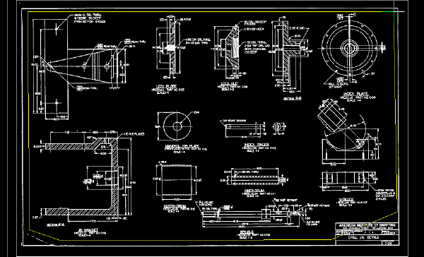
The polygon and all the entities within it now are displayed in red, which indicates they have been captured as part of the REM region object.
Refine the region object
- Click the polygon boundary to select the REM region object.
- Right-click and click Refine Mode. Only the region boundary is highlighted.
- Transparently pan and zoom to the lower-right corner of the image.
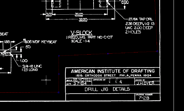
- Select the region boundary. Select the midpoint grip in the title block, and drag this grip to exclude the title block from the region object.
The following example shows how the image should appear after the region object is refined to exclude the title block.
- Right-click and click
Refine Mode from the shortcut menu.
Refine Mode is now de-activated.
Copy the region object to the empty image
- Zoom out to the drawing extents.
- Use the
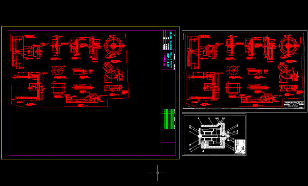
COPY command to copy the region object to the upper-left corner of the empty image.
Create a rectangular region object
- In Image Manager, select Mech_02b, right-click and click Zoom To to see this image.
- Click Rectangular Region
 on the
Raster Entity Manipulation Toolbar.
- Draw a rectangle that includes the entire image: all of the entities, the title block, and the border.
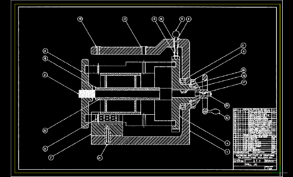
The rectangle and all the entities within it are now red, which indicates they have been included as part of the REM Region object.
Copy the region object
- Zoom to the drawing extents.
- Use
COPY to copy the region object to the lower-left corner of the image that contains the other region object.
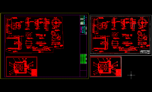
Merge the region objects into the image
- Select the two region objects, right-click, and click
Merge to Raster Image.
After you merge the region objects into the image, the objects are no longer displayed in red because they are no longer region objects. However, the objects in the original images are still defined as region objects.
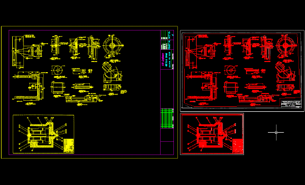
- Right-click and click
REM
 Clear All from the shortcut menu.
The REM region objects are no longer defined in the original images. At this point in a real project, you could save the new image (Mech_new_02) and detach the original source images from the drawing.
- Close the drawing without saving changes.