The following guide is intended for users who need to get up and running with the product quickly. These are the key things you need to know to get the most out of Project Explorer.
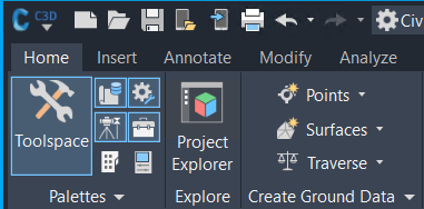
Once installation is complete, the Project Explorer window can be accessed from the Home tab of the main Autodesk Civil 3D ribbon.
Alternatively, Project Explorer can be typed at the AutoCAD Command Prompt.
Working in the Project Explorer Window
The main Project Explorer window is modeless. You can interact freely between the AutoCAD window and the Project Explorer window while the Project Explorer window remains on-screen.
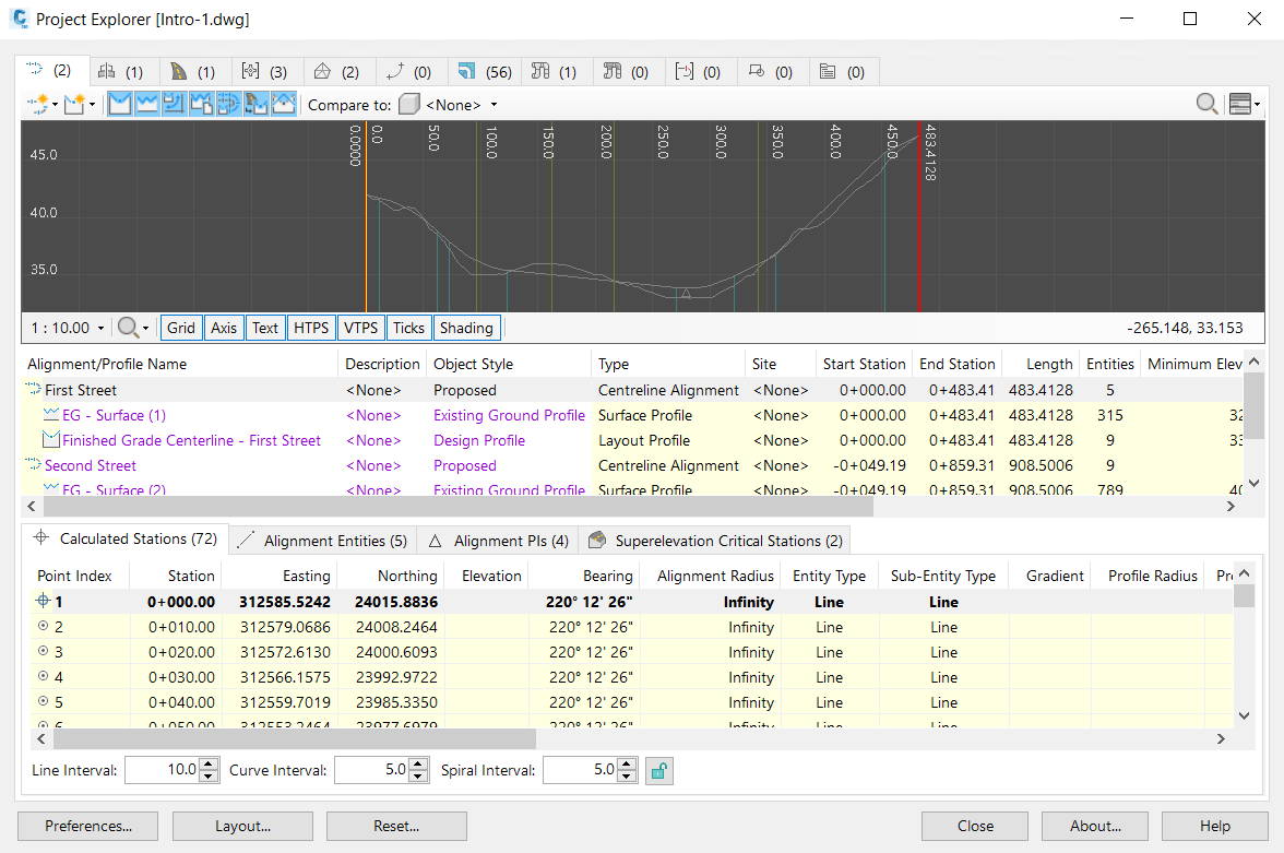
All information displayed in the Project Explorer window is live geometric project data from the Civil 3D model. Therefore, if something is modified or added to the Civil 3D model, the content in Project Explorer will update automatically.
If you use dual monitors, consider keeping Project Explorer open on your second monitor while you work in Civil 3D.
Customizing the Project Explorer Window
The layout of the Project Explorer window and the way that content is displayed within it is fully customizable. There are two different aspects to the customization of the user interface: Layout and Preferences, each controlled from dedicated buttons in the lower left corner of the main Project Explorer window.
User Interface Layout
The layout of content is handled from the Layout Options window, which can be accessed from the Layout... button in the bottom left of the main Project Explorer window. You can use this window to edit the layout, visibility, and name of all data columns. Layout Options can be saved to Layout Styles which can also be used to control the layout of reports and tables.
User Interface Preferences
The remaining options in the Project Explorer window such as fonts, colors, the layout, and visibility of Object Category tabs, and profile view colors and scales, are controlled from the Project Explorer Preferences window.
Right-Click Menus and Keyboard Shortcuts
Most object lists in the panel have right click menus allowing you to select and zoom to the corresponding object in the viewport. You can also press the CTRL button whilst a list has focus to briefly highlight the selected object in the viewport.
Using the Section and Profile Views
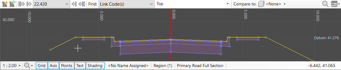
Learn to use the profile viewers which are included in Project Explorer for alignment profiles, sample lines, pipe networks, and assemblies.
Use the scroll wheel to zoom in or out. Hold down the CTRL or ALT button with the wheel to change the scrolling speed. Note that the vertical scale and horizontal scale of these viewers can be scaled independently using the options along the bottom edge of the viewer, or you can select from a preset list of vertical scale exaggeration values.
Generating Reports
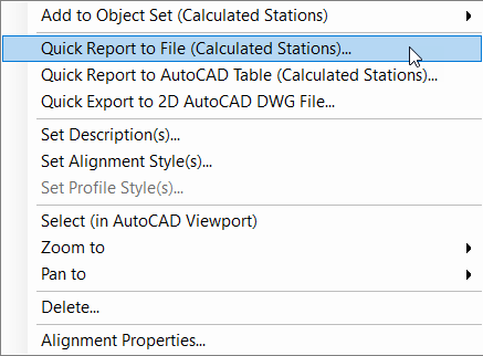
To output a report to a file, right click any listed object in Project Explorer and select either Quick Report or Add to Object Set.
Quick Report
Quick Report generates a dedicated report for the selected object.
Object Sets
Alternatively, the Add to Object Set option sends the object to the Object Sets tab in Project Explorer where each Object Set definition represents a list of objects to be included in an outgoing report. The contents of the Object Sets tab is persistently saved to each drawing. This allows an unlimited number of pre-configured reports to be regenerated between design changes. Use the Generate Report button in that tab to regenerate your reports at any time.
If you add a corridor baseline to an Object Set, you can filter the corridor feature lines that are included in the report.
If you add an alignment or profile to an Object Set, you can add an instruction to run a geometric station (chainage) based comparison with another alignment/profile or surface. Again, these offsets are calculated live so you can continue manipulating those alignments and profiles in Civil 3D and see how that affects the relationship between them.