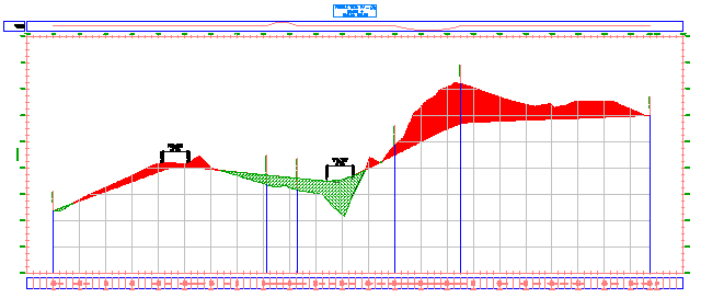
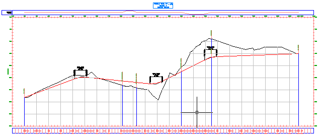
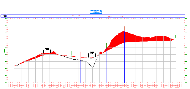
In this exercise, you will illustrate the cut and fill regions along an alignment by applying hatch patterns between the surface and layout profiles.
Hatch patterns can be applied to areas that are formed by two profile lines. Hatch patterns are applied in the Profile View Properties dialog box. You can either specify the area type, or use an existing quantity takeoff criteria. You use shape styles to apply the desired hatch patterns and colors to the areas you have defined.

This exercise continues from Exercise 1: Editing the Profile View Style.
Access the profile view properties
- Open Profile-5B.dwg, which is located in the tutorials drawings folder.
This drawing is similar to the drawings you used in previous profiles tutorial exercises. This drawing contains an additional profile view, Profile View PV - (3), which contains an existing ground and layout profile. You will add hatch patterns that highlight the cut and fill areas between the two profiles.

- Click the Profile View PV - (3) grid to select the profile view. Right-click. Click .
Define a cut area hatch
- In the Profile View Properties dialog box, on the Hatch tab, click
 Cut Area.
 A Cut - (1) area is displayed in the Hatch Area table. For Upper Boundary, the first surface profile in the list is automatically assigned. For Lower Boundary, the first layout profile in the list is assigned automatically.
- In the Shape Style column, click Standard.
- In the Pick Shape Style dialog box, select Cut. Click OK.
- In the Profile View Properties dialog box, click Apply.
The specified shape style is displayed in the cut areas between the profiles.

Define a fill area hatch
- In the Profile View Properties dialog box, on the Hatch tab, click
 Fill Area.
 A Fill - (1) area is displayed in the Hatch Area table. For Upper Boundary, the first layout profile in the list is automatically assigned. For Lower Boundary, the first surface profile in the list is assigned automatically.
- In the Fill - (1) entry, for Shape Style, click the Standard entry.
- In the Pick Shape Style dialog box, expand the list of shape styles.
An appropriate Fill style does not exist in this drawing. You will create one in the following steps.
Create a fill shape style
- In the Pick Shape Style dialog box, select Cut.
- In the Pick Shape Style dialog box, click the down arrow next to
 . Click
  Copy Current Selection.
 - In the Shape Style dialog box, on the Information tab, for Name, enter Fill.
- On the Display tab, under View Direction, select Profile.
- Select both entries in the Component Display table.
- Click one of the Color cells.
- In the Select Color dialog box, for Color, enter 92. Click OK.
- In the Component Hatch Display table, for Pattern, click the Dash entry.
- In the Hatch Pattern dialog box, for Pattern Name, select Cross.
- Click OK four times.
The Profile View Properties dialog box closes, and the new hatch pattern is displayed in the fill areas between the profiles.

To continue this tutorial, go to Exercise 3: Projecting Objects onto a Profile View.