Use this page of the dialog box to review and assign values and settings for the pipes and structures associated with the pipe network.
Data Table
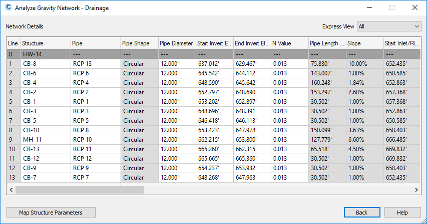
The table on the Network Details page contains the data necessary to perform the selected analysis types.
When you are performing an inlet analysis, additional columns are displayed.
When you click on a row, the corresponding line in the drawing is highlighted. You can access commands to zoom to, pan to, and select a line in the drawing by right-clicking the row and selecting a command on the context menu. Selecting the line selects both the pipe and the structure.
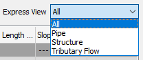
You can control the display of columns by changing the Express View setting, shown below, or by right-clicking the column heading in the table to display the context menu and then selecting the columns you want to be displayed.
Warnings and errors are displayed on this page in the following conditions.
- An error symbol
 with a tooltip is displayed in a cell if the value prevents the analysis from being performed. For example, an error symbol will be displayed if a catchment area or time of concentration is 0.
- A warning symbol
 with a tooltip is displayed in a cell if the value could affect the results but will not prevent the analysis from being performed. For example, a warning symbol will be displayed on a curved pipe to let you know that only its size and start and end elevations may be adjusted during the analysis.
The errors and warnings are also displayed below the table and on the General page of the Analyze Gravity Network dialog box below the Network Details button.
You can click the Map Structure Parameters button to open the Map Drainage Structure Parameters dialog box. You can use the Map Drainage Structure Parameters dialog box to map the parameters of Part Builder parts to parameters that are required for the Analyze Gravity Network command.
Editing Multiple Rows
To edit multiple rows in a column, hold down the Ctrl or Shift keys when selecting the rows and then keep the Shift key pressed when you click the column. If one or more of the selected items in a column is not editable (shown with a gray background), then multiple-row editing is not enabled.
When you select multiple rows, each corresponding line in the drawing is highlighted.
- Line
- Displays each numbered line (a structure and its outlet pipe) in the pipe network.
- Structure
- Displays each structure in the pipe network.
- Pipe
- Displays each pipe in the pipe network.
- Pipe Shape
- Displays the shape of the pipe.
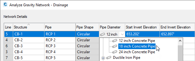
- Pipe Diameter
- Displays the diameter of the pipe.
The available pipe sizes in the pipe network parts list can be selected from a drop-down list.
- Start Invert Elevation
- Displays the invert elevation of the end of the pipe that is in the upstream direction.
- End Invert Elevation
- Displays the invert elevation of the end of the pipe that is in the downstream direction.
- N Value
- Displays the Manning's n value of the pipe.
Note: If Resize Pipes and Reset Inverts is selected on the General page, the value used in the analysis is obtained from the Settings page.
- Pipe Length
- Displays the 3D length of the pipe, measured from the center of the connected starting structure to the center of the connected ending structure.
- Pipe Slope
- Displays the slope of the pipe.
- Start Inlet/Rim Elevation
- Displays the inlet or rim elevation of the upstream structure.
- End Inlet/Rim Elevation
- Displays the inlet or rim elevation of the downstream structure.
- Structure Type
- Displays the type of each structure in the pipe network. Click in the field to display a drop-down list to change the structure type.
Note: The Structure Type for at least one structure should be Grate Inlet, Curb Inlet, or Combination. This defines the structure as an inlet. This property can also be specified for a structure on the Part Properties tab of the Structure Properties dialog box.
- Outfall: If a structure was selected as the Outfall part on the General page, it is shown as Outfall type and cannot be changed.
- Manhole: Specifies that the structure is a manhole.
- Grate Inlet: Specifies that the structure is a grate inlet.
- Curb Inlet: Specifies that the structure is a curb inlet.
- Combination: Specifies that the structure is a combination outlet (curb and grate).
- Reference Surface
- Specifies a reference surface for the structure. A reference surface is used to determine depths and elevations of the pipe network parts, based on rules for the part.
Note: A reference surface is not required; however, when there is a reference surface, the surface elevation will be used to calculate the cover value. If there is no reference surface, the structure rim (typically 0) will be used to calculate the cover value.
- Inlet Location
- Specifies whether the structure is on a continuous grade (On Grade) or in a sag (On Sag) condition. You can click in the field to display a drop-down list to change the structure location.
Note: If an inlet has an Inlet Location of <none>, a warning message will appear for it on the Network Details page and it will not be analyzed in an inlet analysis.
- Bypass Target
- Specifies whether excess flow from the line goes to another line (such as the next structure in the pipe network) or offsite. You can click in the field to display a drop-down list with choices to specify the structure to which the flow is sent to, or you can specify Offsite if the flow is sent to another pipe network or location.
- Structure Shape
- Displays the structure shape.
- Curb Opening Length
- Specifies the curb opening length for curb or combination inlets.
This is the length of the opening in the curb.
- Curb Opening Height
- Specifies the opening height for curb or combination inlets.
This is the height of the opening in the curb.
- Grate Open Area
- Specifies the grate open area for grate or combination inlets. This is the area between the bars of the grate through which water can flow.
- Grate Length
- Specifies the grate length for grate or combination inlets. This dimension is in the direction of flow along the gutter.
- Grate Width
- Specifies the grate width for grate or combination inlets. This dimension is perpendicular to flow along the gutter.
- Local Depression
- Specifies the elevation difference between the inlet opening and the gutter when the inlet is depressed.
- Road Sx
- Specifies the road cross slope.
- Gutter Sw
- Specifies the gutter cross slope.
- Gutter Width
- Specifies the gutter width.
- Longitudinal Slope
- Specifies the slope along the road at the inlet. This property is used for on-grade inlets.
- Gutter n Value
- Specifies the roughness of the gutter material (usually a type of concrete).
- Known Flow
- Optional. Specifies other flow that is not accounted for through the catchment, or it can specify flow to an inlet if a catchment does not exist for it.
Note: If an inlet has no corresponding catchment, and its known flow is 0, it will not be used in any analysis, and it will not be listed in the inlet analysis CSV table.
- Benching Method
- Specifies the benching method: Depressed or Sump, Flat (Level), Half Benched, Full Benched, or Improved. Benching refers to the formation of a channel in the bottom of the structure to provide a smooth transition from the inlet to the outlet. Please refer to the Urban Drainage Design Manual Third Edition, Hydraulic Engineering Circular No. 22 (HEC-22), published by the U.S. Department of Transportation Federal Highway Administration, sections 6.2.5 and 7.1.6.7.
- Catchment
- Displays each of the catchment areas that are associated with each inlet structure.
If multiple catchments reference the same structure, Multiple is displayed in this field.
Note: If no catchments are connected to the structure, you can enter a Known Flow for each inlet, or you can enter values directly into the 2D Area, Runoff Coefficient, and Time of Concentration fields. - 2D Area
- Displays the 2D area of each catchment.
If multiple catchments reference the same structure, the sum of the 2D area of the catchments is shown in this field.
- Runoff Coefficient
- Displays the runoff coefficient of each catchment.
If multiple catchments reference the same structure, the weighted runoff coefficient is displayed in this field.
- Time of Concentration
- Displays the time of concentration that was calculated for each catchment.
If multiple catchments reference the same structure, the longest time of concentration is shown in this field.
Note: If the time of concentration does not meet the default minimum time of concentration specified in the Settings, a warning icon is displayed in the
Time of Concentration field to inform you that the default value will be used in the calculations.