This method minimizes setup time by requiring only a single touch-off point and is performed with the following steps:
- Create a part with multiple Setups, then:
- on the Multi-axis Positioning page of the Stock wizard, select 5th Axis Positioning and click Next; or
- on the Indexing tab of the Stock Properties dialog, select 5th Axis Positioning, and click Fixture Location.
- Select a Setup from the Use Origin of this Setup as the Touch-off Point list. The Z-axis of this setup must be parallel with the A-axis.
- In the
Offset of Touch-off Point from Machine Zero section, enter the distance, in each coordinate system direction, of the 5- Axis Touch-off Point from the center of the A-axis face. This distance is different for each part.
In this example, the X and Y offsets are negative and the Z offset is positive.
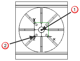
 Center of A-axis face
 Touch-off Setup origin
- For the
First Axis Rotational Offset, enter the angle (measured counter-clockwise) between the spindle axis and the A axis when the B angle is set to 0.
For example, if the A-axis faces the spindle when B is set to 0, then enter 0. If it faces the door when B is set to 0, as in the example below, then enter -90. This offset is set the same for all parts machined on a specific machine.
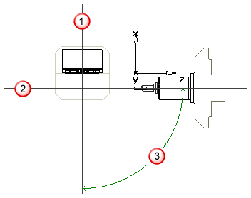 A-axis
Spindle axis
A-axis
Spindle axis
 B-axis rotation
- Select the dominance from:
-
Tool Dominant — If you want the order of operations to be tool dominant across all Setups, select this option.
Note: You must also select Minimize tool changes in the Automatic ordering options dialog for Tool Dominant to work correctly.
-
Setup Dominant — If you want the order of operations to complete each Setup before moving on to another Setup, select this option. The milling ordering attributes determine the order in which operations are performed within a Setup.
Select Generate Single Program if you want to create a single 5-axis indexed program. When this option is selected, you need only specify the simulation information for the first setup and it is used for all setups.
-
Tool Dominant — If you want the order of operations to be tool dominant across all Setups, select this option.
- Click Finish in the stock wizard or OK in the Stock Properties dialog.
- Generate toolpaths. Ensure
Minimize tool changes is selected in the
Automatic Ordering Options dialog if you are using
Tool-dominant toolpaths.
The simulation works for both centerline and 3D simulation. In centerline simulation an arc is displayed for a 5-axis reorientation. In 3D simulation the part position and orientation stays fixed and the tool moves. The tool does not move smoothly between Setups, it reappears in the new Setup.
- Select a 5-axis post processor and create NC code.
- The NC code is generated with respect to the B-axis coordinate system. Only a single touch-off is required to locate the part.
- The Rotary Center Offset values are contained in the post processor files.