You can use the 2D/3D Shaded page to edit the settings which affect 2D and 3D simulations.
Resolution — This controls the quality of the image and affects the speed of the simulation. Set it to a positive value. The default value is 1. If you double the value (by setting it to 2.0), the tool is subtracted from the block half as often. If you decrease the value, the tool is subtracted from the block more often. If the simulation is too chunky, decrease Resolution by half. If the simulation quality is acceptable, but it is running too slowly, double the Resolution.
Power graph samples/min — The tool load graph is determined by measuring the Tool load a certain number of times per minute. The Power graph samples/min is the number of samples to take per simulation minute.
Pause on limits — Select this option to pause the machine simulation if a solid exceeds the limits of movement specified in the Machine Design file.
Show pause on gouge dialog — Select this option to display the Possible Gouge dialog to warn you that a gouge has taken place. See Detecting gouges for more information.
Only Play Sim Once — For some machines with two spindles, the simulation plays through the simulation twice. If you want to see the part simulated only once, select this option.
Translucent tool — Select this option to change the tool of a 3D solid simulation to be slightly transparent.
Translucent part — Select this option to change the stock of a 3D solid simulation to be slightly transparent.
Metallic — If you are using graphics hardware for OpenGL shading, you have the option to have the 3D simulation look metallic.
Tool cutting tolerance - This tolerance affects the fineness of the 3D simulation. If this is set high, the simulation appears more faceted. The lower this tolerance is set, the smoother the simulation appears.
Linearization tolerance — This tolerance affects how curves are divided into small straight lines. Increase this setting to reduce the simulation time for complex parts. This is also affected by the Wrapping tolerance and Turn/mill angular interpolation attributes.
Rotate view when indexing — This setting applies to 4th or 5th axis indexed parts and turn/mill parts. With Rotate view when indexing selected, the simulation rotates the part for an A-axis or B-axis indexing move in milling or for a C-axis rotation in turn/mill. Although these rotations provide a more accurate simulation, they can slow down the simulation especially with simultaneous X- and C-axis moves in turn/mill. To speed up the simulation, deselect this setting and the part stays fixed and the tool moves around the part.
Save result files during RapidCut — Select this option to view intermediate shaded simulations in rapid cut mode. This option is useful if you want to have quick access to images of the part at the conclusion of each operation. This option requires a lot of memory and slows down the simulation process, so we recommend that you use it only when you want to study the results of each operation carefully.
Save result files during 3D sim — You must select this option to enable the Use results as starting point feature.
View independent — Select this option to use our Visicut engine. When using this engine you can pause a 3D simulation and change the view at any time. This simulation method uses a solid model and can be used for any and all 3D simulations. Deselect View independent to use our Pixelcut engine. Pixelcut does not allow you to rotate the model, but the simulation runs considerably faster. Pixelcut is fast, and similar to RapidCut, but it has an advantage over RapidCut in that it can simulate tools with undercuts, and cutting from different directions (3+2). RapidCut is useful if you are cutting a long-running toolpath in 3-axis, such as a mold. Pixelcut is useful if you are cutting a long-running toolpath from multiple directions (3+2).
Show edges — Select this option to outline the edges of the machine during machine simulation.
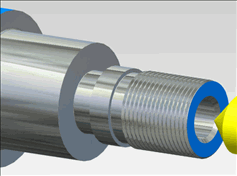
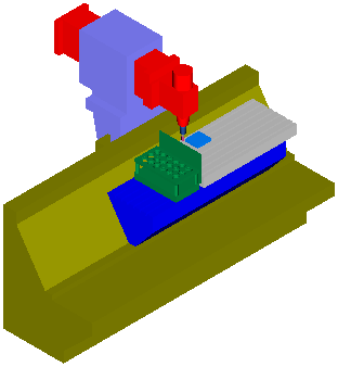
This example shows the default behavior with Show edges deselected:
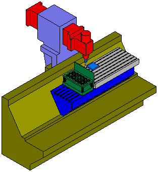
This is the same example with Show edges selected:
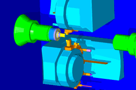
Shadow quality — If you are using graphics hardware for OpenGL shading you can display shadows in your simulation. The image shows an example of shadows displayed when using machine simulation.
If the slider is dragged all the way to the left to None, then shadows are turned off. As you drag the slider to the right the quality of the shadows improves. This option can slow down the simulation.