The exceptions to this rule are listed below. These rules apply to 2.5D milling features.
- Zigzag ramping is not performed for NT Spiral, NT Zigzag, NT Continuous Spiral toolpaths and Vortex when pre-drilling points are used.
- If Max. ramp angle is 0 the tool plunges directly into the feature.
- If you request zigzag ramping (by deselecting the
Helical ramping check box), but
FeatureCAM determines that there is not adequate room for zigzagging then there are two cases:
- if machine can do a helix is selected then zigzag ramp to depth while following the contour of the feature.
- if machine can do a helix is deselected then FeatureCAM plunges directly.
- If Helical ramping is requested, but FeatureCAM determines that there is not enough room, then FeatureCAM follows the rules for zigzag ramping.
Zigzag ramping occurs when the Helical ramping option is deselected. Zigzag ramping typically moves in linear segments. You control the length of these segments with Max. ramp distance and the slope of the linear moves with Max. ramp angle. If you specify a Plunge point, zigzag ramping is still available, but the distance of the ramping moves is calculated automatically. FeatureCAM determines the starting point for milling the feature and the tool zigzags between the plunge point and the automatically calculated start point.
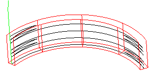
For simple grooves or for plunge points that are located in narrow regions of a feature, straight, linear zigzag ramping may not be possible since these moves would gouge the feature. Instead, the tool will zigzag along a 3D arc or a combination 3D arcs and lines that would follow the shape of the feature. In this case, 3D arc moves are output in the NC code. There is currently no way to approximate these moves with 3D line segments. The Linear approx. parameter only applies to helical ramping.

See also Using zig-zag ramping to mill a helical path for a simple groove.
Helical and zigzag ramping restrictions
FeatureCAM tries to automatically determine locations for ramping into the part using the following criteria:
- The ramping move should not gouge.
- For zigzag ramping, the XY distance of each linear move must be at least one tool diameter for non-center cutting tools. Center cutting tools only need an XY move of 20% of the tool diameter.
- For helical ramping, the same restrictions mentioned above apply, except that the distance applies to each 360
 helical move.
If you ask for ramping and do not receive the ramping move set a Plunge point or pre-drill the entry point.