Turning-head tool holders are supported in FeatureCAM, which enable you to perform turning and boring operations on a milling machine.
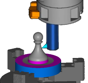
For example, in the image below the piece is machined by the tool rotating around the stock.
4-Axis indexing is supported, but 5-Axis positioning is not.
To create a turning head feature:
- Create a Setup over the center of rotation of the turning head, so that the tool will rotate about the Setup Z axis.
- Create a curve in the XZ plane that defines the profile of the turned shape.
- Load the TurningHeadCS.dll add-in using the Macro Add-ins dialog.
- In the
New Feature wizard, under
From Feature, select
User and click
Next.
The User defined feature page is displayed.
- In the
Registered features list, under
Macro Add-ins, select
Turn Head, and click
Next.
The Curves page is displayed.
- Select the curve in the graphics window and click
Add from selected items
 .
.
- Click Next to display the Location page.
- Click Next to display the User defined feature page.
- Specify the parameters to define the feature. To change a parameter, select the parameter name, select an option in the
New Value list, then click
Set.
Profile — Select a curve to define the turning feature profile.
Toolpath Type — Select whether you want to create an Inside Diameter or Outside Diameter feature.
Rough Stock Curve — Select the curve that defines the toolpath boundary for the feature. Leave this unset to machine to the stock boundary.
Rough Pass — Select True to include a rough operation.
Finish Pass — Select True to include a finish operation.
Cycle Type — Select the cycle type.
In a Turn cycle, the roughing tool feeds along the Z axis while stepping down the X axis.
In a Face cycle, the roughing tool feeds from the outside of the part to the center while stepping down in the negative Z direction.
Cut Direction — Select the direction along the Z axis you want to cut the feature.
U Axis Sign — Select which direction along the U axis the tool is cutting.
- Click Finish to create the Turn Head feature and close the dialog.
- When using two tools on the turning head, create a separate feature for each tool with opposite U Axis Sign selected.
- Use the Tool Block Selection dialog to select the tool block solid as a tool block for the turning tools.
- You may need to adjust the Start point and End point on the Turning tab of the Turn Head Properties dialog for each operation to ensure the tool does not collide with the part at the start and end of the toolpath.
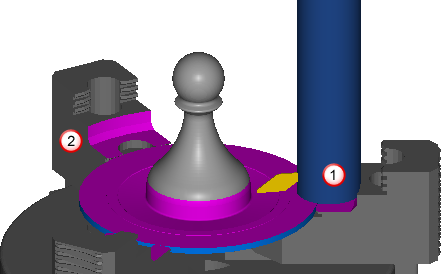
- Run a simulation to check for collisions.
The rotation of the tool is not displayed in the simulation, but the tool is checked for collisions and gouges. For example, in this image the tool has gouged with the clamp at
 , and another gouge is displayed at
 .
.