You can simulate turning head tool holders, which enable you to perform turning and boring operations on a milling machine.
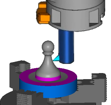
For example, in the image below the piece is machined by the tool rotating around the stock.
To modify a Machine Design file to support turning head tool holders:
- In the Machine Design Settings dialog, ensure Enable Turn/Mill UI is selected, and select Support Specialized Turning Heads.
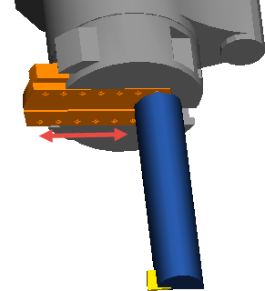
- Create or import solids to represent the turning head tool holder and the plate that moves in the U axis that holds the turning tool.
- Use the Parent/Child Relationships dialog to make the U plate solid a child of the turning head tool holder solid.
- Use the Specify Movement dialog to enable the U plate solid to move in +delta X.
- Create a UCS on the U plate solid to locate the tool.
- Using the Tool Block dialog, make the turning head tool holder solid a tool block, and create a tool location on the tool block using the UCS you created on the U plate solid.
- To use two tools that cut from opposite sides of the part, create a second UCS for the tool location, which is facing the opposite direction to the other tool location UCS, and add the tool location in the Tool Block dialog.