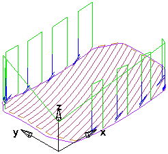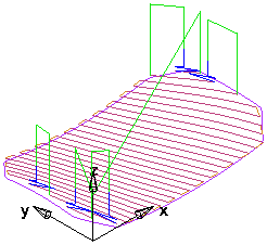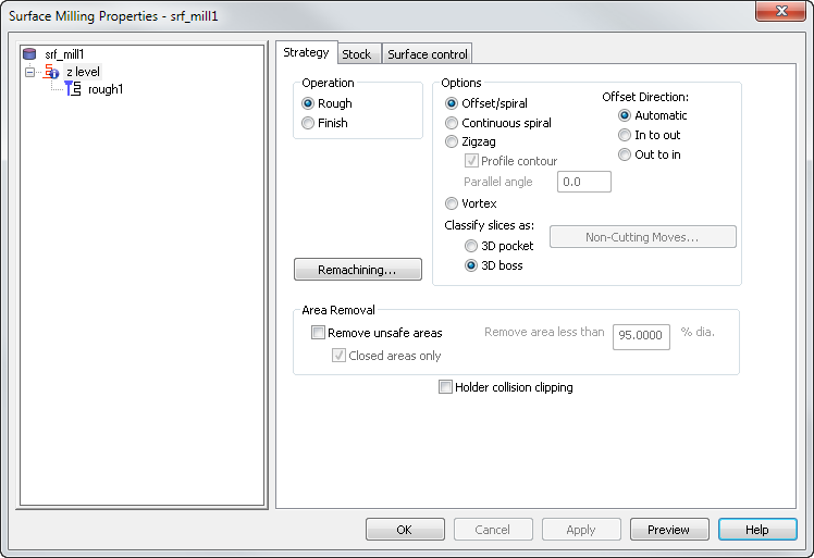
Specify the style of toolpath. If you select Zig-zag, this roughs the part raster-style with an optional profile around each Z-slice (optionally select the Profile contour option).
The value can be anywhere from -360 to 360 degrees, the default is 0.0. A positive value rotates counter-clockwise from the principle axis, and a negative value rotates clockwise from the axis.
|
X parallel, Parallel angle 20
|
Y parallel, Parallel angle 20
|
- Setting the angle to 90 on an X-parallel operation causes it to effectively become a Y-parallel operation.
- Setting the angle to 180 causes the toolpaths to be cut from the opposite side of the part. For example, an X-parallel operation with the angle set to 0 starts at the minimum Y coordinate. With the angle set to 180, the toolpaths start at the maximum Y coordinate.
Continuous spiral — This option enables the tool to move in a continuous smooth spiral motion and reduces tool load.
Vortex — An offset toolpath, which is machined at the specified cutting feed rate almost all of the time. The optimum tool engagement angle is never exceeded, by replacing difficult toolpath segments with trochoids. This works well for solid carbide tools.
Offset Direction:
- Automatic — The tool cuts from the outside to the inside of the stock in a continuous radial movement. This is the default option.
- In to out — The tool plunges into the stock and cuts outwards.
- Out to in — The tool cuts from the outside to the inside of the stock. The tool outlines the surfaces and cuts large sections last.
Non-Cutting Moves — Click this button to display the Vortex Non-Cutting Moves dialog where you can specify whether to retract and increase the feed rate on non-cutting moves for vortex toolpaths.
Remachining — Click this button to open the Z-Level Rough Remachining Options dialog.
Area Removal
Remove unsafe areas — This removes small toolpath segments to prevent tool damage when using non-center cutting tools. When machining into small pockets, removing small segments stops the central, non-cutting underside of the tool from hitting non-machinable material. Unsafe segment removal filters out the machining of confined areas with small movement of the cutting tool.
Remove area less than — This removes segments that are smaller than the entered percentage of the tool's diameter, unless they surround a Boss feature.
Closed areas only — Select this option to remove segments, in enclosed areas, that are smaller than the Threshold value.
Holder collision clipping — Clips the toolpath where the holder or shank collides with a part surface, check surface, or unmachined stock. When selected, the Holder clearance and Shank clearance attributes are displayed on the Milling tab for the operation.
Z-level rough area removal example:
This headlamp mold has two cavities that work their way down into small pockets:
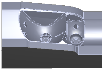
This is a cutaway view of a 3D simulation with Remove unsafe areas deselected:
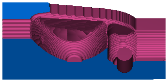
The bottoms of the pockets are barely bigger than the tool diameter, and the tool hardly moves in these areas. The non-center cutting region of the tool cannot cut the material at the bottom of the pockets.
This is the simulation with Remove unsafe areas selected and Remove area less than set to 80 % of the tool diameter:
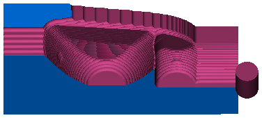
The two smaller pocket regions are removed from the toolpath. This protects the tool and prevents damage.
