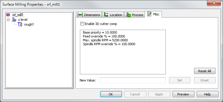
Enable this option to use 3D cutter compensation. For a 3D surface milling feature, 3D cutter compensation compensates for the tool radius in the direction of the contact point. The compensation is not simply right or left. You can use the Misc tab of the Surface Milling Properties dialog to edit the machining options of a Surface Milling feature.
Enable 3D cutter comp — See the 2.5D Strategy tab for more information on cutter compensation.
To use 3D cutter compensation, the .cnc file must support 3D cutter compensation in the linear move format. For example:
{N<SEQ> }{<MOTION> }{<COMP-STAT> }{X<X-COORD> }{Y<Y-COORD> }{Z<Z-COORD> }
<IF><COMP-3D-ON><THEN>
I<X-SRFNORM><32>J<Y-SRFNORM><32>K<Z-SRFNORM><32>
<ENDIF>
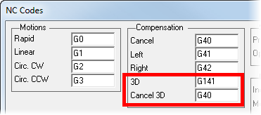
3D cutter comp applies only to finishing operations and linear moves. Any arc lead-ins are approximated by linear moves if 3D cutter comp is selected for the feature. The XBUILD compensation keywords (<COMP-STAT>, <COMP-START> and so on) work for both 2D and 3D cutter compensation (only one type of compensation can be active). Set the NC codes to turn 3D cutter compensation on and off in the NC Codes dialog in XBUILD:
Base priority
Features are sorted by their Base priority to determine the order in which they are manufactured. For features that have the same Base priority value, the system uses the Automatic Ordering settings.
To ensure that an individual feature is cut before anything else, you can set its Base priority attribute. All features have a default Base priority of 10. To ensure that a feature is manufactured first, set its priority to a lower value. To make a feature last, set its priority to a higher value. For example, if you set the Base priority of a pocket to 8, its roughing pass is the first operation performed, its finish pass is second, and the rest of the operations are ordered according to the Automatic Ordering or Manual Ordering settings.
Feed override % — Enter a scaling factor for the feed rates generated by FeatureCAM. A value of less than 100 reduces the calculated feed rates. A value of more than 100 increases the rates.
Max. spindle RPM — Enter the maximum spindle speed (in RPM) that you want to use.
Spindle RPM override % — Enter a scaling factor for the speed rates generated by FeatureCAM. A value of less than 100 reduces the speed rate, and a value of greater than 100 increases it.
Spline tolerance approximates the profile with arcs and lines if a profile is defined as a spline. The smaller the value of the parameter, the smoother the profile.
Z rapid plane — Enter the minimum safe distance in Z above your part.
Before performing a rapid move away from a feature, the tool retracts to the Z rapid plane setting for that feature. The rapid move to the next feature changes in Z height, that is, changes Z coordinates, if the next feature has a different Z rapid plane setting. So that when it arrives at the next feature it is at the Z rapid plane for that next feature.
This value is relative to the top of your stock in the current user coordinate system. Compare with Plunge clearance.