This function creates a parting surface from a curve.
The parting surface constructor does not part the model. Use Cut solid with parting surface or Select core/cavity for that functionality. The curve can be a 2D or 3D curve. The curve can be obtained in many ways including Silhouette Curves, Surface Edges, and Curve projected onto a surface. The Z axis of the UCS indicates the parting direction of the mold. For 3D curves the curve is divided at any corners.
To create a parting surface:
- Select Construct tab > Solids panel > Manufacturing > Parting Surface to display the Parting surface dialog.
- Optionally enter a Name for the solid, or leave the default name.
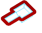
- Enter the Land Width. This is the width of your parting surface.
- Select the UCS you would like to use in the UCS list. The Z axis of this UCS is used as the parting direction.
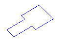
- Select the
Parting Curve from the list and click the
Add
 button or use the
Pick curve
button or use the
Pick curve
 button to select the curve in the graphics window.
- If your curve is 3D, it is broken up, and subdivided at sharp corners, into a number of curves. Each of these names is listed under your curve name.
- Click the Preview button to see your surface.
- Click OK.
Note: If a section of your curve seems to be oriented incorrectly follow the steps below.
To change the direction of a segment of a parting surface.
- Select the curves in the
Curve list to highlight the segment.
The direction is displayed in the Extrude direction field.
- To change the direction, enter a new vector in the form (X,Y,Z). You must enter the parentheses and the commas. For example (1,0,0) is the X direction.
- Click the Set button.
- Click the Preview button to see the results.