You can change and animate parameters such as the colour, specular highlight, shine, and transparency of 3D models. You set these parameters using the Geometry menu. To access this menu, double-click a Geometry node in the schematic, or follow the tab population rules for the Object menu (see Populating Menu Tabs of Selected Objects).
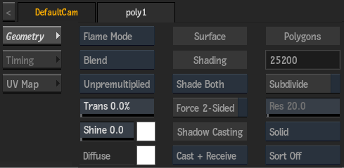
Blending Settings
- Blend Type box
- Select whether to use Flame or Photoshop blend modes.
- Blend Mode box
- Select how the 3D model and the scene are combined. The available list of modes depends on the selection in the Blend Type box. See Surface Blending Modes.
- Transparency field
- Displays the transparency level of the 3D model. Editable.
- Shine field
- Displays the intensity value of the specular highlight. When this value is zero, the specular highlight is disabled. Shine affects both size and intensity. Editable.
- Specular colour pot
- Displays the colour of light reflected by the 3D model's surface. To enable the specular highlight, the Shine value must be larger than 0. Editable.
- Diffuse colour pot
- Displays the diffuse colour. Editable.
Surface Settings
- Shade Order box
- Select the drawing priority of the 3D model normals.
Select: To draw the polygons: Shade Both That are both facing and opposite the camera. Shade Front Facing the camera last. Shade Back Opposite the camera last. This option is especially useful for semi-transparent models
- Force 2-Sided button
- Enable to have lights in the scene light both the inside and outside of the geometry (when shading is turned on).
- Shadow Casting box
- Select how the selected geometry object will be affected by a Shadow Cast object in the scene. See Surface and Geometry Shadow Casters.
Polygons Settings
- Polygons field
- Displays the number of polygons in the 3D model. Non-editable.
- Subdivide button
- Enable to create high-quality shading for polygon models.
- Resolution field
- Displays the geometry resolution of the 3D model. Active when Subdivide is enabled. Editable.
- Wireframe box
- Select a wireframe option for the 3D model. When you render the 3D model with Wireframe or Original Wire selected, it retains its light, shading, and texture attributes.
Select: To: Solid Disable wireframe for the 3D model (filled polygons are drawn). Wireframe Display the model as a wireframe outline (triangular polygons only). Original Wire Display the model as a wireframe outline (original mesh; any polygon type). May be useful for imported geometries.
- Sort box
- Select how the 3D models contained in the scene are drawn.
Select: To: Sort Off Not apply any sorting. Sort All Sort all objects according to the Z-order and the order of the object group (Material ID). Sort Transparency Give transparent objects lower priority than opaque parts, to solve transparency issues if the scene contains semi-transparent 3D models.
Timing Settings
If the 3D model has animation, you can find settings in the Timing tab of the Geometry menu.
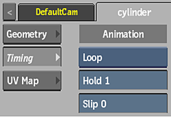
- Animation Mode box
- Select the animation mode to use for multiple 3D geometries imported into a single animated geometry node.
Select: To: Loop Play in a continuous loop. Once Play once. The 3D geometry is no longer displayed. Last Still Play once, and hold the last frame. Timing Animate according to the timing in the animation channel.
- Hold field
- Displays the number of continuous frames for Loop, Once, or Last Still Animation modes. Editable.
- Slip field
- Displays the offset to the start point for Loop, Once, or Last Still Animation modes. Editable.
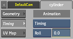
- Timing Range option box
- Select an option to determine how Frame Timing values outside the timing range of the animation are handled. Available when Timing is selected in the Animation Mode box.
Select: To: Roll Roll over the Frame Timing value. Cut (Geometry is not displayed.) Round Display the first or last geometry (with this option, you can select the first and the last geometry of your animation).
- Frame Timing field
- Displays the value for the frame in the timing curve. Available when Timing is selected in the Animation Mode box. Editable.
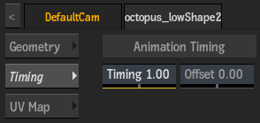
- Timing field
- Displays the scale of the geometry animation. Editable.
- Offset field
- Displays the offset applied to the animation curve. Editable.
UV Map Settings
Use the UV Mapping settings to select how the UV coordinates of an attached displace, normal, or diffuse node are mapped to the 3D model. You can also apply axis transformations to the UV map. These transformations are different from the settings of the parent axis in that they transform the axes of the actual UV map coordinates.
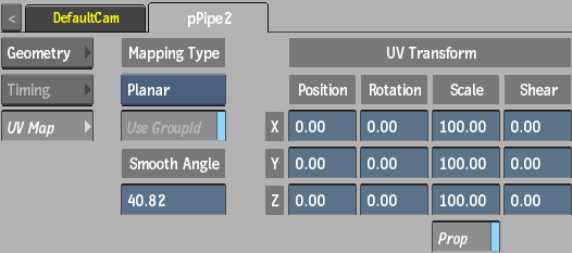
- UV Mapping Type box
- Select the type of UV mapping to apply to the attached node.
When a Displace or Normal node is attached to a geometry, you may need a UV mapping type other than Default for the displace or normal pattern to have any effect on the geometry.
Note: When a Diffuse node is attached to a geometry, you must select Wrap from the Mapping box in the Diffuse menu to be able to use the UV mapping settings. See Diffuse Mapping.
- Use GroupId button
- Enable to respect GroupId information in an FBX file created in 3ds Max.
- Smooth Angle button
- Enable to override existing normals in the geometry, then use the Smooth Angle field to change the value.
- Smooth Angle field
- Displays the angle at which the edges of normals become hard. Changes to this field only affect the shading of the displacement, and not the shape. Editable.
- Position X field
- Displays the position of the X axis. Editable.
- Position Y field
- Displays the position of the Y axis. Editable.
- Position Z field
- Displays the position of the Z axis. Editable.
- Rotation X field
- Displays the rotation of the X axis. Editable.
- Rotation Y field
- Displays the rotation of the Y axis. Editable.
- Rotation Z field
- Displays the rotation of the Z axis. Editable.
- Scale X field
- Displays the scale of the X axis. Editable.
- Scale Y field
- Displays the scale of the Y axis. Editable.
- Scale Z field
- Displays the scale of the Z axis. Editable.
- Prop Scale button
- Scales the X, Y, and Z UV axes proportionally.
- Shear X field
- Displays the shear of the X axis. Editable.
- Shear Y field
- Displays the shear of the Y axis. Editable.
- Shear Z field
- Displays the shear of the Z axis. Editable.