Draw a helical, silhouette, intersection curve, or a curve on a part face. Also generate wire from an intersection curve in composite.
What's New: 2019
Draw a Helical Curve
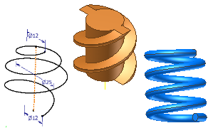
The Helical Curve tool creates constant or variable pitch 3D coil shapes, such as springs and threads. Helical curves can be joined with other sketch entities to create a complex sweep path.
- In an active 3D sketch, click
3D Sketch tab
 Draw panel
Helical Curve
Draw panel
Helical Curve
 .
.
- In the Helical Shape tab of the Helical Curve dialog box, choose a Type:
- Select Constant helical curve to create a helix with a single pitch value.
- Select Variable helical curve to create a helix with multiple rows of parameters you specify in a table.
- Select a Definition type to choose the parameters you want to use to define the curve:
- Pitch and Revolution. Creates a helical curve based on a specified pitch and number of revolutions.
- Revolution and Height. Creates a helical curve based on a specified number of revolutions and a height.
Note: For a variable helix, you must use Revolution and Height values that are in a range greater than the value in the row above and less than the value in the row below.
- Pitch and Height. Creates a helical curve based on a specified pitch and height.
- Spiral. Available for constant helix only. Creates a flat helical curve based on a specified number of revolutions.
- Enter values for the type of shape you specified:
- Diameter (Optional). The diameter of the helical curve. Inventor calculates the diameter automatically based on height, pitch, and revolution. The point on diameter is projected into the plane (normal to centerline) of the start point.
- Height. The height of the helical curve.
- Pitch. The elevation gain for each revolution.
- Revolutions. The number of revolutions must be greater than zero but can include partial revolutions, such as 1.5. If specified, the number of revolutions includes the end conditions.
- Taper (Optional). The taper angle, if needed, for all constant helix types except Spiral.
- Click a Rotation option: Left hand or Right hand.
- On the Helix Ends tab of the Helical Curve dialog box, specify conditions for the Start and End points of the curve:
- Natural
- The distance (in degrees) over which the curve achieves the transition (normally less than one revolution). The following example shows the top with a natural end and the bottom end with a one-quarter turn transition (90 degrees) and no flat angle:

- Flat
- The distance (in degrees) that the curve extends after transition with no pitch (flat). Provides transition from the end of the revolved helical curve to a flattened end. The example shows the same helical curve as the Transition angle in the previous image, but with a half-turn (180 degree) flat angle specified:

- In the graphics window, click to define the start point of the curve and then click to define the end point.
Draw a Curve on a Face
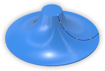
Curve on Face creates an interpolation spline directly on a part face based on your input. You can draw the spline across multiple faces on the same body. Each interpolation point has a coincident constraint to the face.
- In an active 3D sketch, add sketch points or work points on a face and add dimensions to fix their position.
Note: This step is optional. However, for predictable update results we recommend adding and positioning points using this process.
- Click
3D Sketch tab
Draw panel Curve on Face

- In the graphics area, on a part face, draw the curve using existing points, or click to set the first point of the spline.
Note: For cases where multiple entities overlap between two or more bodies, it is recommended that you hide any body that should not participate in the Curve on Face.
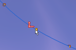
- Continue to click, adding points where needed.
- To close the loop and create a periodic spline, click the starting point. To close a spline, post creation, right-click the end point and choose Close Spline.
- Point - 2D sketch, 3D sketch, spline control point, or work point. A coincident constraint is applied to the selected point and the created curve. The face must be visible. The point must be coincident with the face being drawing upon.
- Edge - a coincident constraint is applied to the selected edge and the created curve. The edge must be part of the shell. Spanning multiple bodies is not supported.
Editing a Curve on a Face
You can also remove the curve association to the face. Right-click the Curve on Face browser node and click Break Link. Constraints for middle points are removed. Endpoints retain their constraints to either a face or curve. These constraints must be removed manually.
Where spline points are also used for other geometry, such as curve endpoints or hole centers, the constraints are preserved.
Draw a Silhouette Curve
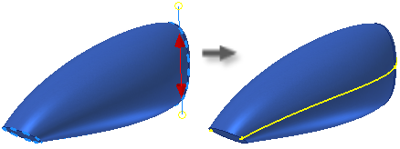
The Silhouette Curve tool creates an associative 3D curve along the edge of a body as defined by a direction vector. Visualize a beam of light shining on an object. The silhouette curve is generated where the light drops off and the shadow begins. Silhouette curves are often used to determine a natural parting line.
- In an active 3D sketch, click
3D Sketch tab
Draw panel
Silhouette Curve
 .
.
- The Body selector is active in the dialog box. In the graphics window, select the Body.
- The selector in the dialog box changes to Direction. Select a work plane, planar face, edge, or an axis to specify the pull direction.
- Optionally, you can exclude geometry from silhouette curve generation by doing the following:
- Choose Faces in the dialog box and then select the faces to exclude from curve generation in the graphics window.
- Check the Exclude straight faces option.
- Check the Exclude internal faces option.
- Click OK to create the curve.
Inventor generates an associative curve along the outer boundary of the surface. Faces that lie in the pull direction are ignored.
- If necessary, add lines or splines to create a closed boundary.
To use the silhouette curve to split an object, generate a Boundary Patch surface from the closed sketch. Use the boundary surface as the Split Tool. If the boundary surface doesn’t split the solid, extend the surface.
- To disable the association, select the silhouette curve in the browser, right-click, and choose Break Link from the context menu.
Draw an Intersection Curve
- In an active 3D sketch, click
3D Sketch tab
Draw panel
Intersection Curve

- In the graphics window, click a face, surface, 2D sketch curve, work plane, or part body to define the intersection.
- Click one or more faces, surfaces, 2D sketch curves, or work planes to intersect.
- Click OK to create the curve.
Generate Wire from Intersection Curve in Composite
- Import surface data to a composite feature.
- Generate a surface which intersects the composite feature.
- Start a new 3D sketch.
- In the 3D sketch, click
3D Sketch tab
Create Panel
Intersection Curve.
- Select the composite and the surface.
- Click OK.
3D curves are generated in the 3D sketch at the intersection point. Curves update when intersection bodies are updated.