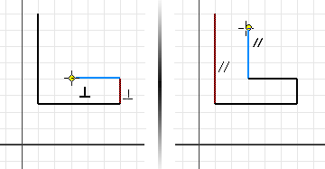
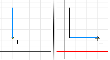
Enable Constraint Inference
Use the Constraint Settings dialog box to specify the default behavior for how constraints are inferred and persist.
- Click Sketch tab
 Constraint panel
  Constraint Settings
  .
. - On the Inference tab of the Constraint Settings dialog box, choose an option:
- Infer Constraints. When selected, constraints are inferred to the geometry created with the active command.
- Persist Constraints. Available only if Infer Constraints is selected. When Persist Constraints is selected, constraints are created automatically after you finish a sketch. If Infer Constraints is selected and Persist Constraint is deselected, constraints are not created automatically after finishing a sketch but the Inference position is correct.
Note: Coincident constraints at end points of lines are always inferred and persistent unless you deselect the Coincident option under in Selection for Constraint Inference. This behavior prevents the creation of open sketch profiles. - Under Constraint Inference Priority, choose the preferred constraint type for automatic placement of constraints:
- Parallel and Perpendicular. (Default) Looks first for constraints that define relationships between geometry, and then looks at the coordinates of the sketch grid.

- Horizontal and Vertical. Looks first for constraints that define the orientation of sketch geometry in relationship to the sketch coordinates, and then looks for constraints between sketch geometry.

- Parallel and Perpendicular. (Default) Looks first for constraints that define relationships between geometry, and then looks at the coordinates of the sketch grid.
- Under Selection for Constraint Inference, select any or all of the constraints to be inferred. Note: If Infer Constraints is not enabled, you can’t select any constraints to infer.
- Click OK.
Specify Constraints and Geometry Available for Inference 
When the Infer Constraint option is selected in the Constraint Settings dialog box, you can specify what geometry is used to infer constraints when creating new geometry.
- Click Sketch tab
 Constraint panel
  Constraint Inference Scope
  .
. - In Constraint Inference Scope dialog box, choose the geometry to use to infer constraints:
- Geometry in Current Command. (Default) Constraints are inferred to the geometry created with the active command.
- All Geometry. Constraints are inferred to all active sketch geometry.
- Select. Lets you select the sketch geometry to which constraints are inferred.
- Click OK. Tip: Regardless of which scope option you specify, you can infer constraints from any geometry by pausing the cursor over that geometry when you’re creating it. Conversely, prevent constraint inference while sketching by pressing Ctrl while creating new geometry.
Enable Relax Mode
Relax Mode allows you to modify geometry and apply new constraints to geometry that is already constrained. When enabled, you can freely drag selected sketch geometry even if it is constrained, and conflicting constraints are removed when you add new dimensions. When Relax Mode is off, dragging geometry does not remove existing constraints or dimensions.
- Click Sketch tab
 Constraint panel
  Constraint Settings
  .
. - On the Relax Mode tab of the Constraint Settings dialog box, select Enable Relax Mode.
- Under Constraints to Remove in Relax Dragging, select any or all types of constraints to show or hide.
- (Optional) Select Preserve Dimensions with Equations to prevent dimensions from changing when you drag a line that is controlled by an equation.
- Click OK.