The idea that geometry within Autodesk Inventor behaves differently due to the application of constraints often hinders new users transitioning from a 2D drawing application.
- 2D and 3D sketch constraints control geometry within sketches
- Assembly constraints and joints establish relationships between components in an assembly that control position and behavior.
Within the Autodesk Inventor sketch environment, there are two types of constraints: geometric and dimensional.
The status bar at the bottom of the graphics window indicates the number of dimensions required to fully constrain a sketch. As you sketch, apply geometric or dimensional constraints to reduce this number to zero and fully constrain, or stabilize, your sketch geometry.
Geometric Constraints
Geometric constraints are created automatically between lines, arcs, and other geometry as you sketch. Constraints can also be manually applied after the sketch geometry exists to stabilize sketch shape or position. These geometric constraints allow the sketch to be edited with predictable results. For example, dragging the endpoint of a line that’s constrained to be perpendicular to another line does not change the perpendicularity.
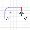
Constraints are inferred when sketching new or modifying existing geometry. This process of inference decides which constraints are available to the geometry as the shape and orientation are varied. As a constraint is inferred, the constraint symbol is shown, as well as dotted alignment lines, if applicable.
Constraint persistence determines if inferred constraints are maintained after the geometry is created. If constraint persistence is turned off, constraints are not created automatically. Varying inference and persistence settings can affect the results of sketch operations.
Dimensional Constraints
Parametric dimensions , a type of sketch constraint, control the size and position of geometry. Dimensions are created automatically when you enter values in the input boxes as you create geometry or manually using the General Dimension command. Dimension values can be expressed as numeric constants, as variables in an equation, or in parameter files.
Edit a dimension to change the size of the associated geometry. You can edit sketch dimensions before or after a sketch becomes part of a feature. If a sketch has not been consumed by a feature, its dimensions are visible and can be edited. After a sketch is consumed by a feature, select the feature in the browser and activate the sketch for editing.
If applying a dimension would over-constrain the sketch, you can accept or cancel the dimension. If you accept the dimension, the dimension is saved as a reference parameter, its value is enclosed in parentheses, and it updates in response to changes in normal dimensions.
You can also choose how dimensions are displayed using options in the status bar at the bottom graphics window. Choose from Value, Name, Expression, Tolerance, or Precise Value. Dimensions calculated by equations (where, for example, d5=d2) are displayed with the prefix "fx."
Normal vs. Driven Dimensions
In the Inventor sketch environment, dimensions can be categorized into two types: normal dimensions and driven dimensions.
Normal, or general, dimensions are parametric dimensions that determine the size of sketch geometry – they “drive” the geometry. When you change the value of a normal dimension, the geometry resizes accordingly.
Driven dimensions, conversely, are nonparametric dimensions that show the current value of geometry. Their values are driven by changes made to the geometry; you can’t edit driven dimensions to resize geometry. Driven dimensions, which appear enclosed in parentheses in the graphics window, allow sketch geometry to dynamically respond to associated changes.
Dimensional Tolerance and Properties
It’s impossible to manufacture parts to exact dimensions. The closer to an exact size an item or feature must be manufactured, the more expensive it becomes. Conversely, the part may not function correctly if the tolerance range is too large. That’s why, as you apply dimensional constraints, you can specify tolerance for sketch dimensions. Depending on the type of part you’re sketching and its purpose, there is a range of acceptable tolerances for each dimension.
A company standard usually establishes the allowable tolerance for dimensions. Set up your company standards as defaults in the Document Settings dialog box and specify standard tolerances and a default tolerance. Add a row for each unique combination of precision level and tolerance range.
Degrees of Freedom
The ways in which sketch geometry can change size or shape are called degrees of freedom. For example, a circle has two degrees of freedom: its center and its radius. An arc has four degrees of freedom: center, radius, and end points.
If you eliminate all degrees of freedom by applying constraints or dimensions, the sketch is fully constrained. If any degrees of freedom remain unsolved, the sketch is under-constrained. As you create geometry, Autodesk Inventor displays Degrees of Freedom glyphs to illustrate whether geometry is unconstrained, partially constrained, or fully constrained.
As constraints are applied to the geometry and degrees of freedom eliminated, the glyphs disappear. Conversely, as constraints are deleted and degrees of freedom added, the glyphs appear. Use the degrees of freedom glyphs to help you determine how to apply geometric and dimensional constraints to your sketch geometry.
Tips for Working with Sketch Constraints
- Stabilize shape before size. Apply geometric constraints before dimensions so that the sketch shape is less likely to distort.
- Use both geometric constraints and dimensions. Some constraint combinations can distort under-constrained portions of the sketch. If distortion occurs, delete the last constraint placed and consider using a dimension or a different constraint combination.
- When possible, use auto-dimension. Use the Dimensions command to add only the dimensions you need, and then use the Automatic Dimensions and Constraints command to calculate all other sketch dimensions and constraints.
- Place dimensions on large elements before small ones. To minimize distortion, first define large elements that tend to determine sketch size. Dimensioning small elements first might restrict overall size. Delete or undo a dimension if it distorts the shape of the sketch.