Slice through model to display half, quarter, or three-quarter views.
What's New: 2019.2
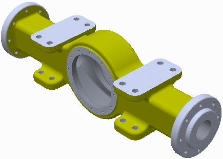
Create a section view to see inside your model. A section view does not modify geometry.
Use a planar face or plane to slice away a portion of a model temporarily.
Section views can be saved in design view representations.
After you select a section view, you can right-click and select Flip to cycle through available views. Quarter and three-quarter views can show the opposite view.
To move a section plane, right-click and select Virtual Movement  Section Plane 1 (or Section Plane 2). Then drag the section plane, set its offset, or rotate the mouse wheel.
Note: Both the quarter or three-quarter section view allow selection of any two planes, not just perpendicular planes. You can define the type of section cut and display sectional slices, if desired.
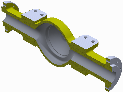
Create a Half Section
- Click
View tab
Appearance panel
Half Section View
 .
.
- Select any plane or planar face as the cutting plane.
- Right-click and select Flip, if necessary, to change the direction of the section.
- Drag the plane or enter a value in the field to change the position.
- Click Continue.
- Right-click then select:
- OK to apply the section.
- Flip to change the direction of the section.
- Virtual Movement > Section Plane 1 to change the position of the plane.
Create Quarter and Three-Quarter Sections
- Click view tab Appearance panel and then select a section view type:
- Quarter Section

- Three Quarter Section

- Quarter Section
- Select any plane or planar face as the first cutting plane.
- Right-click and select Flip, if necessary, to change the direction of the section.
- Drag the plane or enter a value in the field to change the position.
- Click Continue.
- Select any plane or planar face as the second cutting plane.
- Right-click and select Flip, if necessary, to change the direction of the section.
- Drag the plane or enter a value in the field to change the position.
- Click Continue.
- Right-click then select:
- OK to apply the section.
- Flip to change the direction of the section.
- Three Quarter Section View to change the section view type.
- Virtual Movement Section Plane 1 or Section Plane 2 to change the position of the plane.
Note: In Inventor, components created from Content Center are not sectioned by default. Check the Section All Parts box on the Assembly tab in the Application Options to section Content Center parts. Click Tools tab
Options panel
Application Options to access the Application Options.
Revert to Normal View
- Click
View tab
Appearance panel
End Section View
 . The model returns to the normal view.
Modifying the Section Capping Plane Texture
Use your own texture image for the capping plane texture or color. Capping plane texture images are scaled for each part in an assembly.
- Use the image editor of your choice to create a texture or color BMP image. It must be BMP format. Save the image to a disk location
- In Inventor, click
Tools tab
Options panel
Application Options
Color Tab.
- In the Section Solid Texture dropdown list select Bitmap Image.
- Click the file browse button, then, navigate to and select the texture image you want to use.
Controlling the Scroll Wheel Step Size
You can specify an incremental value that is applied when you roll between scroll wheel detents during the section view command.
- Start the Section View command.
- Right-click in the display and in the context menu, click Scroll Step Size.
- In the dialog, specify the distance value used by the scroll wheel as you roll it.
- Click the green check to close the dialog box. Subsequent mouse wheel rolling uses the specified value.