Create circles, ellipses, rectangles, slots, polygons, fillets, and chamfers.
When creating 2D shape geometry, first select a part face or work plane to use as the sketch plane. In an empty file, select the sketch plane and then start to sketch.
Create Circles
- Click Sketch tab
 Create panel and choose one of the following:
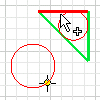
- Center Point Circle
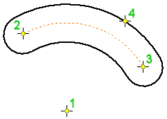
 . Creates a circle defined by a center point and a point on its radius. The first click sets center point; the second click specifies the radius. A tangent constraint is applied if the second point is on a line, arc, circle, or ellipse.
- Tangent Circle
 . Creates a circle defined by a center point and a point on its radius. The first click sets center point; the second click specifies the radius. A tangent constraint is applied if the second point is on a line, arc, circle, or ellipse.
- Center Point Circle
- Click in the graphics window to set the circle points or tangent lines.
- Move the cursor to preview the circle radius or tangent lines.
- Continue to create circles as needed.
- To quit, press Esc or click another command.
Create Ellipses
The Ellipse tool creates an elliptical shape with a center point, a major axis, and a minor axis that you define. You can trim and extend ellipses like any other curve.
- Click Sketch tab Create panel Ellipse
 .
.
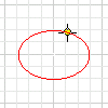
- In the graphics window, click to create the ellipse center point.
- Move the cursor in the direction of the first axis, indicated by a centerline. Click to set the direction and length of the axis.
- Move the cursor to preview the length of the second axis, and click to create the ellipse.
- To quit, press Esc or click another command.
Tip: When you Offset an ellipse, the result is either a mathematical ellipse or an associative spline.
If you select an ellipse near a quadrant and an axis is visible, the offset geometry is an ellipse. If you select an ellipse between quadrants and an axis is not visible, the offset geometry is a spline.
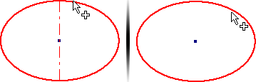
An offset ellipse is a nonassociative mathematical ellipse. An offset spline is associative to the shape of the original ellipse. You can create a dimension between the spline and ellipse to control the offset distance.
Create Rectangles
The rectangle tools create rectangles from a corner or center point in two or three clicks.
- Click
Sketch tab
Create paneland choose one of the following:
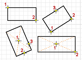
- Two Point Rectangle
 . Creates a rectangle using two clicks that define diagonal corner points. Two-point rectangles are aligned with the sketch coordinate system.
- Three Point Rectangle
 . Creates a rectangle by defining the length, direction, and the adjacent side. The first click sets a corner, the second click sets the direction and distance of one side, and the third click sets the distance of the adjacent side. A three-point rectangle can have any alignment.
- Two Point Center Rectangle
 . Creates a rectangle by defining the center, width, and length of the shape. The first click sets the center point; the second click sets a corner.
- Three Point Center Rectangle
 . Creates a rectangle by defining the center, direction, and the adjacent side. The first click sets the center, the second click sets the direction and distance of one side, and the third click sets the distance of the adjacent side.
- Two Point Rectangle
- Click in the graphics window to set the first point.
- Move the cursor and click to set the second and third points, depending on the type of rectangle you’re drawing.
- To quit, press Esc or click another command.
 Show Me How to Draw a Two Point Center Rectangle
Show Me How to Draw a Three Point Center Rectangle
Create Slots
- Click Sketch tab Create panel and choose one of the following:
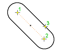
- Center to Center Slot
 . Creates a linear slot by defining the placement and distance of slot arc centers, and then the slot width. The first two clicks specify the arc centers, and the third click specifies slot width.
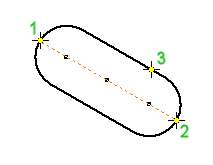
- Overall Slot
 . Creates a linear slot by defining the slot’s orientation, length, and width. The first two clicks specify the start and end point of the slot center line. The third click specifies slot width.
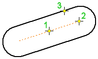
- Center Point Slot
 . Creates a linear slot by defining the slot center point, the arc centers, and the slot width. The first click specifies the center of the slot. The second click specifies the center of a slot arc. The third click specifies slot width.
- Three Point Arc Slot
 . Creates an arc slot by defining a center arc and the slot width. The first two clicks sets the start and end points of the slot center arc; the third click sets the center of the slot arc. The last click specifies slot width.
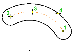
- Center to Center Slot
 . Creates an arc slot by defining the slot’s center point, the end points of the center arc, and the slot width. The first click sets the center point of the slot; the second and third clicks set the start and end points of the slot center arc; the fourth specifies slot width.
- Center to Center Slot
- Click in the graphics window to set the first point.
- Move the cursor and click to set the second, third, and fourth points, depending on the type of slot you’re drawing. Alternatively, enter the values in the edit field or right-click and enter a value.
- To quit, press Esc or click another command.
Create Polygons
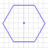
The Polygon tool creates polygons with up to 120 sides.
- Click Sketch tab Create panel Polygon
 .
.
- In the Polygon dialog box, choose one of the following options:
- Inscribed. Uses the vertex between two edges to determine the size and orientation of the polygon.
- Circumscribed
 . Uses the midpoint of an edge segment to determine the size and orientation of the polygon.
- Enter the number of edges you want the shape to have.
- Click in the graphics window to set the center of the polygon and then drag to create the shape.
- To quit, press Esc, click another command, or click Done in the Polygon dialog box.
Create Fillets
The Fillet tool creates rounded corners (vertices) at the intersection of two selected lines. You specify the radius of the fillet arc, which is tangent to the curves trimmed or extended by the fillet. You can create fillets on perpendicular or parallel lines, concentric arcs, intersecting and nonintersecting arcs, elliptical arcs, splines, or between arcs and lines.
- Click Sketch tab Create panel Fillet
 .
.
- In the graphics window, select the lines that you want to fillet.
- In the 2D Fillet dialog box, enter a Radius. and click Equal to create fillets with equal radii.
To preview the fillet, move the cursor over an endpoint shared by two lines.
Note: Intersecting lines are trimmed to the ends of the fillet arc. - (Optional) Enter a different radius. The radius remains in effect until you change it.
- Continue to select lines to fillet, as needed.
- To quit, press Esc, click another command, or close the 2D Fillet dialog box.
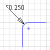
Create Chamfers
The Chamfer tool creates a beveled corner at the intersection of any two nonparallel lines.
- Click Sketch tab Create panel Chamfer
 .
.
- In the 2D Chamfer dialog box, specify whether dimensions options:
- Create Dimensions
 . Select to include aligned dimensions in the sketch that indicate the chamfer size.
- Equal to Parameters
 . Sets the distance and angle of additional chamfers to the value of the first-created chamfer in the current instance. Equal to Parameters is On by default. Deselect it to assign numeric values to chamfers.
- Create Dimensions
- Select the type of chamfer you want to create, and enter distance values:
- Equal Distance
 . Defined by the offset distance from the point or intersection of the selected lines.
- Unequal Distance
 . Defined by a specified distance from the point or intersection for each selected line. Enter Distance 1 and Distance 2.
- Distance and Angle
 . Defined by an angle from the first selected line and a distance offset from the intersection of the second selected line. Enter a Distance and Angle.
- Equal Distance
- In the graphics window, select the lines that you want to chamfer.
- Create additional chamfers if desired.
- To quit, press Esc, click another command, or click OK in the 2D Chamfer dialog box.