Organize the properties of bends and their sequence.
- On the ribbon, click
Annotate tab
 Table panel
General .
Table panel
General .

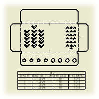
- On the drawing sheet, select a flat pattern drawing view of a sheet metal part.
-
In the Table dialog box:
 Click Column Chooser and add or remove columns from the bend table.
- Set format of the BEND ID string.
- Click OK to close the dialog box.
- Place the table on the drawing sheet.
Note: Alpha character Bend ID relies on the specific character set of the language used during installation. As an example, the bend order number ‘27’ would be displayed as ‘AA’ if the Alpha option was selected and the language of installation was English.
Tip: To exclude particular characters from the alphanumeric auto-indexing sequence, change the Character Exclude options on the General tab of the Standard Style panel.
Create bend tags
Bend tags are added to the selected drawing view automatically after the bend table is inserted in the drawing.
To add bend tags in a drawing view manually:
- Right-click the bend table.
- Select Add Tags to View from the menu.
- Select the drawing view to place bend tags.
Edit a bend table
Renumber bends, change bend direction, or add dual dimension values.
- Right-click a bend table, and select Edit from the menu.
- Make the desired edits in the Edit Table dialog box:
- Click Renumber to renumber items in the table consecutively according to the current order. The initial numbering rules for the bend table are respected.
- Right-click the Bend Direction column and select Reverse Direction to revert the direction for bends in the table.
- To display dual dimension values in the bend table, click Column Chooser
. Then add the alternate unit column to the table by using the Column Chooser dialog box.
- Click Apply to save changes, and OK to close the Edit Table dialog box.
Tip: For more procedures, see
To Edit a Table.