How notes and tables are used to add bend and punch instructions.
Bend Annotations
A bend note adds fabricating information to sheet metal bend centerlines. Bend notes are associated with a drawing view.
A bend table lists propertied of all bends in a flat pattern view of a sheet metal part.
Bend tags associate rows in a bend table with the view geometry. After you insert the bend table in the drawing, bend tags are added to the selected drawing view automatically. Bend tags are formatted by the Dimension style, and do not have a leader by default. Drag the bend tag text away from the original position to add a leader to the bend tag.
Notes:
- Each individual bend centerline is treated as an individual bend object in the drawing (with respect to both bend notes and bend tables). In the sheet metal model, the number of bend centerlines is not equal to individual bend features. (The contour flange, contour roll, lofted flange, and hem features produce multiple bend centerlines in one operation).
- Contour Roll and Cosmetic centerline features are automatically collected into any generated bend table.
- Contour roll centerlines do not report KFactor or direction information.
- Depending on the attributes applied during creation, Cosmetic centerlines can produce empty fields or custom formatting of text strings in bend tables or notes.
- To change the Bend ID sequence, open the sheet metal part, edit the flat pattern, and change the Bend Order.
- If the Bend Order sequence has been modified, the resulting sequence of Bend IDs within any bend table can require sorting using the Table Edit functionality.
- The bend direction in the bend table corresponds to the direction of bends in the selected view. If you select a sheet metal part file as the source for a bend table, the default bend direction is displayed in the bend table. To revert the bend direction, edit the bend table, right-click the Bend Direction column, and select Reverse Direction.
- To correct the bend direction in legacy drawings, drag the bend note or table to a new position.
- Bend tables are not associated with a drawing view. The bend table is not deleted if you delete the drawing view selected on creating the bend table.
- If the selected sheet metal file does not contain a flat pattern or contains a flat pattern created in Inventor 2010 or earlier using the DataM unfolder, the file is not recognized as a valid table data source.
- Bend Tables for sheet metal materials provide values for the bend allowance at specific bend radii and bend angles for a given material thickness, and have no relation to Bend Tables in drawings.
Punch Annotations
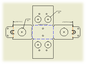
A punch note includes data related to the punch, for example the punch ID, angle, direction, depth, quantity note, and so on. The default style of punch notes is set on the Notes and Leaders tab of the Dimension Style panel.
Before you create a punch table, recover punch centers. Punch centers are represented by center marks in a drawing view. If you create a view-based hole table and select to include recovered punch centers, all visible punch center marks are included in the hole table as individual rows. The corresponding tags are created in the drawing view.
Use the Hole Table command to create a punch table. If appropriate, change Default Filters in Hole Table Style to include recovered punch centers in the hole table by default.
Notes:
- Punch Direction in punch notes and tables is determined by the drawing view. If Punch Direction is DOWN for a punch in a punch note or table related to a front view, it is UP for the same punch in a back view.
- To correct the punch direction in a legacy punch table, drag the punch table to a new position.
- The appearance of punch features in the drawing view corresponds with the representation selected in the model. If punch features are fully formed in the model, visible and hidden model edges are displayed in the drawing view.
- Punch centers cannot be individually unloaded from the drawing view. The only way to remove a recovered punch center is to edit the view and cancel the selection of the Recover Punch Centers option. Any annotations attached to punch center marks are deleted.
- Set the visibility of punch centers by using the Visibility option in the context menu. To display hidden punch center select Show Hidden Annotations in the context menu of the drawing view.
- Center marks associated with punch centers cannot be moved or rotated, but the center mark extensions can be independently resized by dragging.
- When flat pattern drawing views display punch centers, center marks are added, moved, and deleted to reflect any change in the source sheet metal file.
- Unconsumed punch centers in the punch feature sketch are not displayed as recovered punch centers.
- The default formatting for recovered punch centers is specified by the active style. To edit the punch centers style, open the Object Defaults Style panel and change the setting for Visible Simplified Representation and Hidden Simplified Representation.
Alternate units in bend and punch annotations
Bend and punch notes can display dimension values in alternate units. Set the dual units display on the Alternate Units tab of the Dimension Style.
To display dual dimension values in a bend or punch table, add the alternate unit columns to the table by using the Column Chooser dialog box.