These results reveal whether the simulation predicts that a part or parts will deflect upward during the build and interfere with the recoater blade. The acceptable amount of deflection is determined before the simulation by the Recoater tolerance value set in the Solver Settings dialog, Analysis tab. For more information on this setting, see Solver Settings.
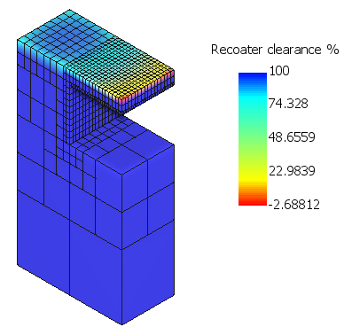
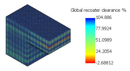
Recoater clearance shown at one increment, and globally for the build
The Recoater clearance % results shown above apply to a simulation using the default Recoater tolerance value of 80%. In this case, recoater clearance values of less than 20% are unacceptable, and we see such values at the increment shown. You can use the Animation panel on the Results tab to step through the recoater clearance % results for each increment of the simulation.
Global recoater clearance % results display, in one view, the full range of clearance values for the entire simulation.
The Recoater status results shown below apply to the same simulation and increment as the Recoater clearance % results above. Here we see that recoater blade interference was detected at the increment shown, so Recoater tolerance was exceeded.
Global recoater status results display the binary value of recoater status for the entire build: 0 for no interference, or 1 for interference detected. We see, in one view, all the locations where interference was detected. The global results for both recoater clearance and status are very useful for seeing these results at a glance, and comparing the results across multiple simulations.
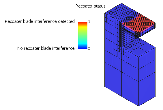
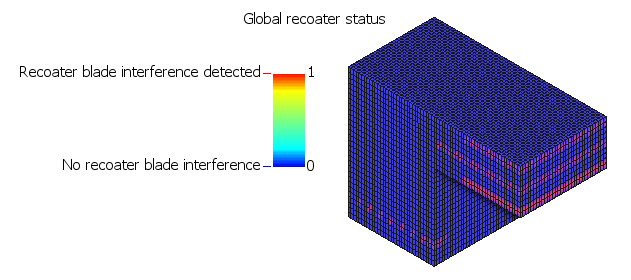
Recoater status shown at one increment, and globally for the build