Camera controls using buttons and mouse input
Jump to:
- Standard Perspectives
- To adjust the perspective view with the mouse
- To center the view on a location
- To adjust the perspective with the perspective indicator
- To adjust the perspective with the viewcube
- To switch between perspective indicator and the viewcube
- To pan the platform about the display
- To zoom
Standard perspectives
There are seven standard perspectives available to choose from: One in every direction along each cardinal axis, as well as an isometric view.
To switch between the standard perspectives:
- Click
View >
 Perspective and choose one of the listed perspectives. These are also available through the context menu of the
viewcube.
Perspective and choose one of the listed perspectives. These are also available through the context menu of the
viewcube.
- Cycle through the perspectives by pressing the Space key.
To adjust the perspective view with the mouse
The mouse provides some more freeform ways to change the view:
- Click and hold the right mouse button and move the mouse in any direction to rotate, or orbit, the view about the center of the display.
Tip: Use the O key to constrain the orbit mode: When constrained, any left-right rotation happens about a vertical axis on the platform bottom, and this axis is then only allowed to tilt straight towards or away from the camera. When unconstrained, or free, any left-right rotation happens around a vertical axis that is parallel to your display.
Free orbit (left) and constrained orbit (right)
- To rotate the camera view clockwise or anti-clockwise when orbiting freely is enabled, right-click close to the edge of the display and move the mouse. This method is not available when orbiting is constrained.
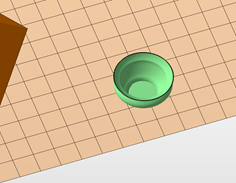
To center the view on a location
When rotating, or orbiting, the camera, it does so around a point within the display space. The point is visualized with a green dot that appears whenever the camera is rotated or the pivot point is relocated.
- Click
 View >
  Center View on Point, then click a point on the part.
- Right-click any point on a part surface and choose
Center View Here from the context menu to make this point the center of camera rotation.
You can also relocate the pivot to a new place on the surface of a mesh, or in empty space without centering the view on it: Use Shift+Middle-click at the desired point in the display.
TopTo adjust the perspective with the viewcube
The viewcube has click-sensitive areas along its faces, edges, and corners. Clicking these turns the cube, and the view, directly towards the front, towards the camera.
You can also right-click the viewcube to choose from the standard perspectives in the viewcube's context menu.
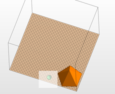
TopTo adjust the perspective with the perspective indicator
An indicator in the bottom left of the display visualizes the current perspective with a representation of the build platform coordinates.

Three different perspectives and the perspective indicator in the matching orientation.
The colored planes in the indicator are interactive: Use them to change the perspectives:
- Click on the blue plane to switch between the views along the Z-axis (top and bottom)
- Click on the red plane to switch between views along the X-axis (left and right)
- Click on the green plane to switch between views along the Y-axis (front and back)
- Click on an X, Y, or Z axis label to align that axis straight out from the display.
To switch between perspective indicator and the viewcube
From the main menu, switch
 Settings > Settings > Display >
  Coordinate system >
  Viewcube between
Viewcube and
Planes.
Viewcube between
Viewcube and
Planes.
To pan the platform about the display
- Hold the middle mouse button and move your mouse around the display.
- Alternatively, or if your mouse doesn't have a middle mouse button, you can hold the Ctrl key and hold the right mouse button.
To zoom
To zoom into or away from a part:
- Use the scroll wheel on your mouse to roll in and out of the viewing screen.
- Hold Shift and the right mouse button and move the mouse forward to zoom in, back to zoom out.
- Press Q to zoom in or A to zoom out.
- Click
View > Zoom to and choose one of the following zoom options:
-
 Zoom to Parts
The view centers and zooms in on all available parts.
-
 Zoom to Selected Parts
The view centers and zooms in on all selected parts.
-
 Zoom to Platform
The view centers and zooms in on the whole platform.
-
 Zoom to All
The view centers and zooms in on all parts and the whole platform.
-
Zoom to Selected Area
After clicking this option, specify the view area for the view by holding the left mouse button and dragging a selection rectangle.
While in this area selection mode, you cannot select parts. To leave this mode mode, press F3 or click
 Select in the toolbar.
A selection rectangle
Netfabb zooms into the area
-