GUI elements explained
Jump to:
Project tree elements
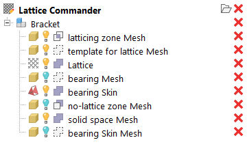
A component named Bracket with a number of bodies comprising it in the project tree.
-
 A
component represents a working set of
meshes,
skins, and
lattices, including
surface lattices. You can have multiple components loaded at once, and they are independent and do not interfere with each other. The elements inside a component are called
bodies.
A
component represents a working set of
meshes,
skins, and
lattices, including
surface lattices. You can have multiple components loaded at once, and they are independent and do not interfere with each other. The elements inside a component are called
bodies.
-
 An actual
mesh. When beginning to generate lattices and hollow bodies ("skins"), a mesh is generally where you begin your work.
An actual
mesh. When beginning to generate lattices and hollow bodies ("skins"), a mesh is generally where you begin your work.
-
 A
skin is the dataset of a mesh where its triangles have been assigned a thickness. Effectively, a skin is the dataset of a hollow part.
Note: A skin is not a mesh, but you can turn it into one.
A
skin is the dataset of a mesh where its triangles have been assigned a thickness. Effectively, a skin is the dataset of a hollow part.
Note: A skin is not a mesh, but you can turn it into one. -
 A
lattice is the dataset of a volume-filling beam structure. Usually, such a lattice has been generated from a mesh.
A
lattice is the dataset of a volume-filling beam structure. Usually, such a lattice has been generated from a mesh.
-
A
surface lattice is the dataset of a structure derived from a mesh's wireframe.
Note: Lattices and surface lattices only differ in how they were generated. Other than that, there is no difference between them, they are both collections of beams and junctions.
Roles
The
role specifies how a body is handled when a part is generated from a
component.
- Bodies can be
 solid, meaning that they appear in the final output.
- Mesh bodies can also be used as stencils, inside or outside of which lattices are kept or eliminated (
 trimming and
 voiding, respectively).
- And of course, you can set them to be
 ignored.
Roles are also automatically set for an existing body you use it to create a new one. You can adjust this by checking or unchecking the relevant options in the context view whenever you are about to create the new body.
- Keep: Keeps the old body in the tree. Helpful for when you want to perform more actions based on this body later.
-
Hide: When the original body is kept, it can be switched from
 visible to
 invisible.
-
Exclude from part output: When the original body is kept, it is set to be
ignored from the part output.
Part generation
To generate a mesh part on the original platform, several methods are available, each with their specializations, advantages and drawbacks.
- Generate part mesh (the default): Rasterizes the component and generates a triangle mesh from that. Creates regular-shaped triangles of uniform size. Forms neater junctions and follows rounded surfaces best, reproducing organic curves most faithfully, including lattice beams, but is slow and produces a high amount of triangles.
- Generate part mesh (legacy): Builds and assembles bodies from as few triangles as possible. It generates larger triangles and observes hard edges best, and is fast, but can create bulbous junctions and artifacts in tight spaces as well as where bodies meet.
- Generate part for FEA: generates the volumetric, linear tetrahedral mesh and directly writes the NAS file suitable for finite-element analysis. Clicking this will ask you for the desired file name of the NAS file to write.
Rasterization options
- Mesh resolution: The body surface is rastered with triangles of about this side length.
- Blend distance: Smoothes orientations of adjacent triangles to create more rounded transitions. Too large a blend distance can produce unprintable lattice as significant downskin areas are created that would require supports.
Lattice meshing options (legacy only)
- Smoothing: The otherwise simple discrete faces of the beams and their junctions are subdivided and their transitions made gradual. This generates a significant amount of triangles costing easily dozens of Gigabytes of RAM for realistic lattices. Use with care.
- Beam side count: To approximate the ideal, cylindrical beams, discrete faces are used. While this number has no significant effect when smoothing is used as well, matching the side count to the angles and the count of beams meeting in a junction can help make the junctions less bulbous.
The four variants of smoothing: None, coarse, fine, superfine.
Thickness gradient options
-
Relative: Adds the gradient value to the current thickness.
Note: It is currently not possible to provide negative values to achieve a thinning effect. As a workaround, use a lower thickness as initial value, then apply the gradient.
- Only apply within bounds: If start or end lie within the space occupied by the lattice, you may choose whether the provided start and end thickness should be applied to the beams beyond the bounds, too.
- Affect whole beam: Normally, beams are reshaped conically to provide a smooth gradient. If this is enabled, the gradient is made up in discrete steps of cylindrical beams.