Jump to:
General parameters
| Parameter | Explanation | Notes |
|---|---|---|
| Description | Provide a custom name to identify the support action at a glance. Particularly helpful when you have the same action multiple times for a staggered approach to supporting parts. | |
| Cluster | See Cluster detection reference (separate page) | |
| Anchors | See Anchors | |
| Connection to bouquet structure | See Connection to bouquet structure | |
| Root system | See Root system | |
| Project bar | See Project bar | |
 Maximal bar height
|
After sprouting from the supported downskin, bars are at most this long regardless whether they connect to anything with their bottom end. |
|
| Support properties |
See Bar Supports reference (separate page) |
Anchors
| Parameter | Explanation | Notes |
|---|---|---|
| Anchor distance |
Defines the space between two anchor points or bars |
|
| Contour offset to wall |
Anchors keep a distance from a cluster contour that borders a wall (a concave border). |
|
| Free contour offset |
Anchors keep a distance from a cluster contour that does not border a wall. |
|
| Add bars to medial axis |
Adds a single row of bar supports to a stretch of supportable area where that stretch would otherwise be too narrow to be eligible under the given, regular contour offset. |
|
|
Down-oriented points
|
Adds a single bar to local minima within a cluster |
|
|
Corners
|
Places bars in sharp corners first. Helpful to ensure support to corners in case the interval between area or border bars happens to leave them out. |
|
| Medial axis contour offset |
Adds the bars to eligible area stretches only if the stretch is at least twice this wide. |
|
|
Borders
|
When set to no, the cluster's contour is left unsupported |
|
|
Rasterize area
|
When set to no, the cluster's area is left unsupported |
|
| Anchor alignment |
Switches between rectangular and hexagonal anchor placement for area-filling bar support |
|
|
Z range limitation
|
Even when a downskin cluster spans a greater height range, only those anchors sprout bars that lie within the minimum and maximum values specified here. |
Connection to bouquet structure
| Parameter | Explanation | Notes |
|---|---|---|
| Connection to bouquet-structure |
When active, bars are merged into trunks before reaching their lower end on part or platform. |
|
|
Diameter of bouquet-structure |
Defines the maximum diameter of single bouquet structures. Smaller diameters cause creation of more, and smaller, bouquets. |
|
| Height of bouquet-structure |
Enforces a minimum distance between the first branch of a bouquet structure and the part. |
|
| Recursive depth of bouquet-structure |
Sets the limit of branches per bar between the first branch and the part. |
|
| Bouquet-structure type |
Netfabb knows two methods to bundle bar supports together. The classical one picks one main bar and grows additional bars from it or from other bars that originate on the main bar themselves ("side branching"). The other, newer method uses proper iterative splitting of bars into ever thinner ones to ultimately cover the cluster's entire surface area with supports ("split branching"). Side branching
Split branching
 Side branching (left) and split branching (right). Note how the selected one on the left goes all the way from the part surface to the bottom, and how other beams "sprout" from it, whereas on the right, the branches split evenly. |
|
|
Maximal vertical bar gradient
|
Ensures that no bar in a bouquet ends up angled further away from the vertical than this threshold, even when the parameter height and diameter would permit it. If necessary, the bouquet height is increased beyond specification, and if this is not enough, a new bouquet is started. If that's not possible either, the bar is projected as an individual one as usual. |
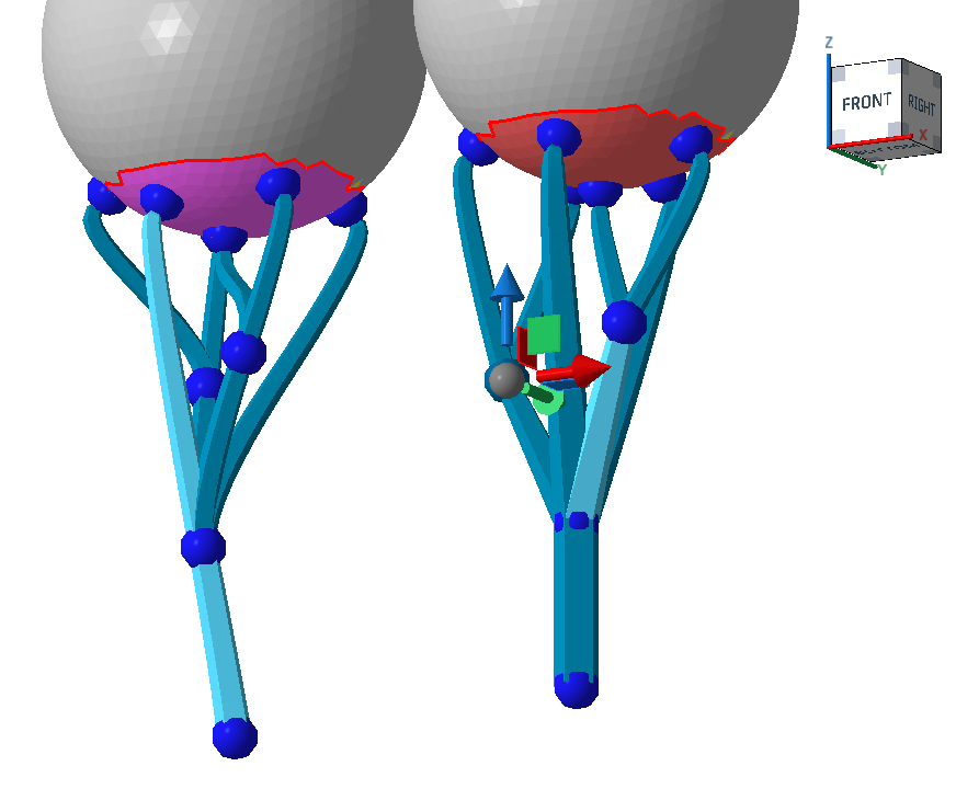
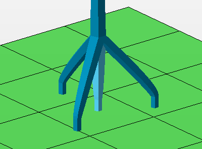
Root system
When active, the bottom of the bars are multiplied to form a tree-root-like structure that reinforces the adherence of individual bars.
| Parameter | Explanation | Notes |
|---|---|---|
| Number of legs |
 The count of legs includes the center one. |
|
| Height |
At this height above the platform or the bottom part surface, measured along the center leg, the side legs merge with the main bar. |
|
| Diameter |
The side bars terminate at a circular contour of this diameter parallel to the build platform. If the bars meet a suitable surface before or beyond this imaginary circle, such as when they terminate on an uneven part surface, the bars are shortened or extended appropriately to maintain the side bar angle. |
Project bar
| Parameter | Explanation | Notes |
|---|---|---|
| Project bar |
Controls angling bar support entities to preferrably hit or avoid part surface. Options
|
|
| Maximum projection angle |
When a bar support entity is eligible for angling, Netfabb attempts to angle (up to a specifiable maximum) and pan the bar to terminate it on the desired part or platform surface. If no suitable angle or panning is found, the bar is projected vertically as usual. |
|
| Surface normal for direction |
To find the final angle of a bar support entity, the surface angles on both ends of the bar are taken into account. Using this percentage value, you adjust the weighting of either surface angle in the calculation of the bar's angle. between 0 % (the vertical) and 100 % (downskin angle).
Note: The
maximum projection angle still applies.
|
 Upskin projection