Options and their function explained
Jump to:
- Cluster Detection
- Edge with Polyline Support
- Area with Volume Support
- Area with Bar Support
- Area with Polyline Support
- Down-oriented Point Bar Support
- Surround Volume by Polyline
- Skeleton with Polyline
- Delete support
- Base plate
- Adaptive Lattice Bars
Cluster Detection
| Parameter | Description | Notes |
|---|---|---|
|
Minimal, Maximal area |
The size of a detected cluster's area must be fully within the range specified here, or it is disregarded for the respective support action. |
|
|
Critical angle |
Areas of down-facing triangles angled at least this much away from the horizontal, highlighted in red, must be, and at minimum are, supported. Adjust this to meet your machine's and material's requirements. |
0-90 ° |
|
Noncritical angle |
Areas of down-facing triangles angled at least this much away from the horizontal, highlighted in yellow, may be supported if they border on enough critically or non-critically angled triangles. Adjust this to smooth the support contour or to merge small clusters of critical angle. |
0-90 ° |
|
Cluster type |
The Type classifies clusters by the angle between triangle normals along their borders. If more than 75 % of a cluster's border length is formed by bordering triangles with converging normals, a cluster is considered concave. If more than 75 % of bordering triangles have diverging normals, the cluster is considered convex. In between, they are considered neither.
Tip: To restrict supporting to those areas which are neither convex nor concave, support the convex and concave ones first and follow up with a catch-all while disallowing duplicate support.
|
All, Concave, Convex, Non-concave, Non-Convex |
|
Duplicate support |
With this option you can control whether triangles of a cluster should get supported with the respective action even when a previous action in the script has already applied support to the same triangles. By overlapping supported areas like that, you can create stepped support density that is stronger where the downskin's angle is particularly shallow, for example. 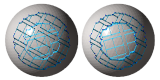 This sphere was supported with a script that included two actions with different values for cluster detection each. The smaller cluster was determined first (with a critical angle smaller than the larger cluster's). Left: Duplicate support tolerated. Right: Avoided.
Note: Technically, this compares the detected clusters first before generating the actual supports. This means that if you have two support actions that both detect the
same clusters, the second action (set to avoid duplicate clusters) does
not generate any supports even when there would be space in the cluster to fit. For such cases, set this to tolerate duplicate support and also set
Keep distance to support to
Yes.
|
Avoid, Tolerate |
|
Cluster inside or outside |
Clusters are considered inside when they belong to a fully enclosed cavity (a hollowing shell) with no connection to the outer skin. |
All, Inside, Outside |
|
Keep distance to support |
When the clusters detected by separate support actions overlap each other, the supports generated by actions further down in the listing keep a distance to supports generated by earlier actions. |
No, Yes |
|
Distance to other support |
When distance to other supports is requested, this amount is kept as the distance. |
|
|
Minimal, Maximal area above part |
A detected cluster's down-projected area must only be intruded into by other mesh (same or different part) to a fraction specified by this range, or it is disregarded for the respective support action. |
0-100 % |
|
Minimal, Maximal z height |
Any point in a detected cluster's area must lie within the z height range specified here, or the entire cluster is disregarded for the respective support action. |
|
|
Respect CAD face groups |
When a cluster is found to intersect with one or more face groups, every section thus created is handled as if it were a separate cluster. |
No, Yes |
A half-cut hollow sphere which contains a concave and convex cluster. A script can include several cluster types with different actions, like polyline supports or bar supports.
TopEdge with Polyline Support
| Parameter | Description | Notes |
|---|---|---|
|
Minimal, Maximal edge length |
Edges beyond the range of lengths specified here are disregarded for applying supports. |
|
|
Maximal polyline curvature |
Sets the curvature that a polyline may have at most. If this maximum value is exceeded, a new polyline begins. |
0-180 ° |
|
Maximal edge angle to XY-plane |
Describes the maximum angle between an edge and the XY-plane. If the maximum angle is exceeded, the edge is disregarded for applying supports. |
0-90 ° |
|
Create anchor on curvature |
Defines on which curvature of the edge a new anchor point is added. The anchor points are created around the edge. |
0-180 ° |
|
Neighbor area angle |
0-90 ° |
|
|
Anchor distance |
Sets the distance between two anchor points. |
1-100 mm |
|
Contour offset |
Sets the distance between an anchor point and a clear area. |
0-5 mm |
|
Startpoint distance |
Sets the border distance between the edge and the start of the support structure |
0-5 mm |
|
Reinforcement lines per side |
Adds additional polyline supports parallel to edges for reinforcement. (This parameter was called differently in the previous version.) |
0-5 |
|
Reinforcements distance |
The additional parallel polyline supports will be this far apart. (This parameter was called differently in the previous version.) |
0.01-10 mm |
|
Support properties |
See Polyline Supports reference. |
Area with Volume Support
| Parameter | Description | Notes |
|---|---|---|
|
Cluster |
Refer to the Cluster Detection section. |
|
|
Contour accuracy |
Specifies maximum permissible deviation when following a cluster's contour |
0.01-0.50 mm |
|
Contour offset to wall |
Enforces a distance between a cluster contour and a wall (a concave border). |
0.01-5.00 mm |
|
Free contour offset |
Enforces a distance between a cluster contour and the next edge (a convex border). |
0.01-5.00 mm |
|
Support properties |
See Volume Supports reference. |
Area with Bar Support
| Parameter | Description | Notes |
|---|---|---|
|
Cluster |
Refer to the Cluster Detection section. |
|
|
Anchor distance |
Defines the space between two anchor points or bars. |
|
|
Anchor alignment |
Switches between rectangular and hexagonal anchor placement. |
|
|
Contour offset to wall |
Anchors will keep a distance from a cluster contour that borders a wall (a concave border). |
|
|
Free contour offset |
Anchors will keep a distance from a cluster contour that does not border a wall. |
|
|
Add bars to medial axis |
Adds a single row of bar supports to a stretch of supportable area where that stretch would otherwise be too narrow to be eligible under the given, regular contour offset. |
|
|
Medial axis contour offset |
Adds the bars to eligible area stretches only if the stretch is at least twice this wide. |
|
|
|
Even when a downskin cluster spans a greater height range, only those anchors sprout bars that lie within the minimum and maximum values specified here. |
|
|
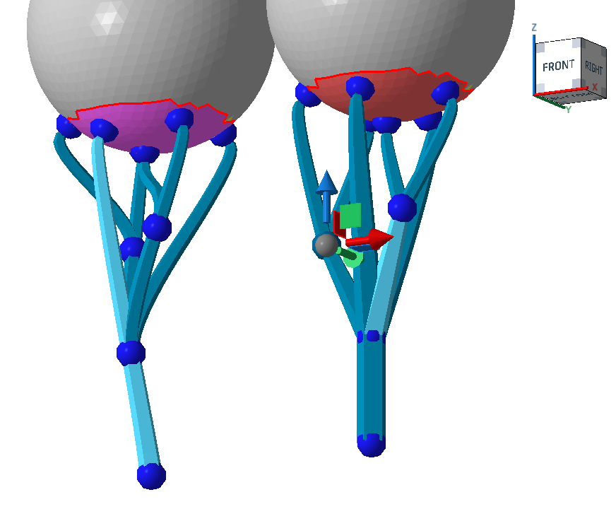
Connection to bouquet-structure |
When active, bars are merged into trunks before reaching their lower end on part or platform. |
|
|
Diameter of bouquet-structure |
Defines the maximum diameter of single bouquet structures. Smaller diameters cause creation of more, and smaller, bouquets. |
|
|
Height of bouquet-structure |
Enforces a minimum distance between the first branch of a bouquet structure and the part. |
|
|
Recursive depth of bouquet-structure |
Sets the limit of branches per bar between the first branch and the part. |
|
|
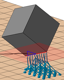
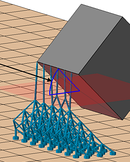
Bouquet-structure type |
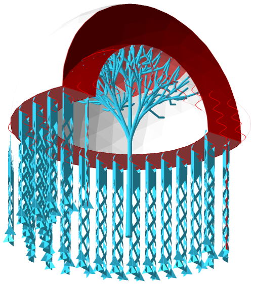
Netfabb knows two methods to bundle bar supports together. The classical one picks one main bar and grows additional bars from it or from other bars that originate on the main bar themselves ("side branching"). The other, newer method uses proper iterative splitting of bars into ever thinner ones to ultimately cover the cluster's entire surface area with supports ("split branching"). Side branching
Split branching
 Side branching (left) and split branching (right). Note how the selected one on the left goes all the way from the part surface to the bottom, and how other beams "sprout" from it, whereas on the right, the branches split evenly. |
|
|
Root system |
When active, the bottom of the bars are multiplied to form a tree-root-like structure that reinforces the adherence of individual bars. |
|
|
Number of legs |
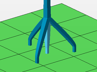 The count of legs includes the center one. |
|
|
Height |
At this height above the platform or the bottom part surface, measured along the center leg, the side legs merge with the main bar. |
|
|
Diameter |
The side bars terminate at a circular contour of this diameter parallel to the build platform. If the bars meet a suitable surface before or beyond this imaginary circle, such as when they terminate on an uneven part surface, the bars are shortened or extended appropriately to maintain the side bar angle. |
|
|
Project bar |
Controls angling bar support entities to preferrably hit or avoid part surface. Options
|
|
|
Maximum projection angle |
When a bar support entity is eligible for angling, Netfabb attempts to angle (up to a specifiable maximum) and pan the bar to terminate it on the desired part or platform surface. If no suitable angle or panning is found, the bar is projected vertically as usual. |
|
|
Surface normal for direction |
To find the final angle of a bar support entity, the surface angles on both ends of the bar are taken into account. Using this percentage value, you adjust the weighting of either surface angle in the calculation of the bar's angle. between 0 % (the vertical) and 100 % (downskin angle).
Note: The
maximum projection angle still applies.
|
|
|
Support properties |
See Bar Supports reference. |

 Upskin projection
Area with Polyline Support
| Parameter | Description | Notes |
|---|---|---|
|
Cluster |
Refer to the Cluster Detection section. |
|
|
Anchor distance |
The detected area will supported with polylines. The anchor distance defines the space between two anchor points for each polyline. |
|
|
Hatch distance |
Sets the distance between two polylines. |
|
|
Rotate by Z |
Rotates the arrangement of the polylines by the entered value. |
|
|
Wave amplitude |
Defines the distance between every intermediate anchor point from a polyline. A value >0 creates a wave (if polyline is smoothed) or a zig zag pattern (if polyline is not smoothed). |
|
|
Offset to border |
Enforces a distance between the cluster contour and the end points of the polylines. |
|
|
Support properties |
See Polyline Supports reference. |
Down-oriented Point Bar Support
| Parameter | Description | Notes |
|---|---|---|
|
Cluster |
Refer to the Cluster Detection section. Results of cluster detections are the blunt tips you may filter for with the switch Supported tip shape. |
|
|
Anchor distance |
Sets the distance between two anchor points or bars. In this way, support between two bars close to each other can be avoided. |
|
|
Supported tip shape |
Both single vertices ("sharp tips") as well as convex clusters ("blunt tips") may be eligible for receiving bar support. With this switch, you can restrict bar support creation to either of them. |
All, Sharp, Blunt from cluster detection, Sharp outside cluster. |
|
Support properties |
See Bar Supports reference. |
Surround Volume by Polyline
| Parameter | Description | Notes |
|---|---|---|
|
Minimal, Maximal edge length |
Edges beyond the range of lengths specified here are disregarded for applying supports. |
|
|
Border type |
The settings help to prevent the polyline from merging with any part wall, if it's set to free border. Border to wall will only place polylines when there is a wall next to the edge. |
All, Free border, Border to wall |
|
Contour type |
The action can also be performed on inner contours where it is not the outer edge of the cluster. |
All, Inner contour, Outer contour |
|
Support properties |
See Polyline Supports reference. |
Skeleton with Polyline
| Parameter | Description | Notes |
|---|---|---|
|
Cluster |
Refer to the Cluster Detection section. |
|
|
Minimal edge length |
Defines the distance between the cluster's contour and the cluster's volume supports that is required for a skeletal polyline to be created. |
|
|
Contour offset to wall |
The anchor points along the contour can be moved further apart from the edge. The offset describes the distance from the edge to the next wall. |
|
|
Free contour offset |
Describes the distance between an anchor point and the next edge. |
|
|
Offset to border |
This determines the length of the skeletal reinforcements in narrow cluster sections. The skeletal polyline is extended towards the wider portions of the cluster until its end is at least this distance away from the closest point in the cluster's contour. |
|
|
Support properties |
See Polyline Supports reference. |
Delete support
| Parameter | Description | Notes |
|---|---|---|
|
Above z value |
Supports entirely above this value get deleted. |
|
|
Below z value |
Supports entirely below this value get deleted. |
|
|
Entity type |
Restricts the support deletion to the desired type. |
All, Entity bar, Entity polyline, Entity volume. |
Base plate
| Parameter | Description | Notes |
|---|---|---|
|
Offset |
Determines the margin to generate the contour of the base plate. The margin is added to the shadow area of the part as well as to any contours of solid volume support structures at their termination on the build platform. |
|
|
Height |
Determines the thickness of the base plate. |
|
|
Fill inner contour |
If the shadow area and the area occupied by solid volume support produces fully enclosed areas, this switch determines whether they should also be covered by the base plate.
Note: Enclosed areas are only tested for
before the margin is applied. This switch therefore ignores any areas that (would) become enclosed by overlapping offsets of neighboring shadow or support areas.
|
Adaptive Lattice Bars
This is an area-supporting action. It subdivides the determined support into unit cells which are then filled with lattice topology. From the scaffolding thus created, individual bars support the respective downskin clusters. If possible, and desired, whole groups of eight cells (2×2×2) are collapsed into single cells.
| Parameter | Description | Notes |
|---|---|---|
| Cluster |
Refer to the Cluster Detection section. |
|
| Anchor distance |
Defines the space between two anchor points or bars on the cluster surface. This is independent from the lattice cell size. |
|
| Anchor alignment |
Switches between rectangular and hexagonal anchor placement on the cluster surface. This is independent from the lattice cell topology which has always a quadratic cross section. |
|
| Contour offset to wall |
Anchors will keep a distance from a cluster contour that borders a wall (a concave border). |
|
| Free contour offset |
Anchors will keep a distance from a cluster contour that does not border a wall. |
|
| Cell width and Cell height |
Determines the size of the smallest cell, and indirectly the angle of diagonal support bars. You should keep the ratio of width to height above a certain value so as to keep the diagonal bars printable. |
|
| Adaptive steps |
The rule of collapsing multiple fully intact lattice cells into the next larger cell size is applied up to this many times. Note that this is only the permissible maximum. If there aren't enough intact cells in a contiguous 2×2×2 arrangement, no collapsing is performed. |
 Comparison of adaptation. Three adaptive steps lighten the lattice considerably more than just one step. |
| Distance part to lattice |
This minimum distance is enforced between lattice and part surface when hugging the surface contours with the lattice scaffolding. |
|
| Lattice go around the part |
If enabled, a wider volume in a pyramid-like fashion is created and filled with lattice. This fills even more volume with rigid support but consequently consumes significantly more buildspace on the platform. When disabled, only as many cells are used as is necessary to cover the part's shadow area. Depending on part geometry, this can mean that downskins higher up are supported only with regular bars that themselves connect part-surface-to-part-surface. |
|
| Single down point tips |
With this switch, this support action can also see to supporting downward-facing protrusions whose sides do not qualify for cluster detection such as when they are steeper than the critical and non-critical angles. This is off by default. |
|
| Sharp edges |
Toggle to support down-facing edges with a line of additional bar supports each |
|
| Maximum edge angle to XY plane |
Specify a "critical angle" for the edge itself below which an edge is eligible to receive edge support |
|
| Neighbor area angle |
Specify a "critical angle" for the surface that itself is not critical but terminates in an edge you still want to have supported. |
|
| Support properties |
See Bar Supports reference. |