Triangles cutting through each other create conflicts for slicing and other processing steps
Self-intersections occur when triangles or surfaces of shells cut through each other. Once detected, self-intersections are highlighted with a red line. The line is visible even when the self-intersections occur inside or on the back side of the part. If surfaces lie on top of each other, all triangles associated with the double surface are colored orange.
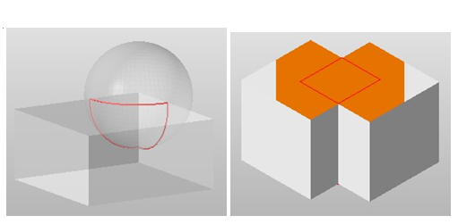
Left: Cutting line of a self-intersection. Right: Triangles belonging to a double surface inside the part are marked in orange.
To detect self-intersections
- In the context view, switch to the Actions tab.
- Click
Detect to identify any self-intersections in the model.
Tip: You can also right-click in the display and choose
 Detect Self-Intersections from the context menu.
To split off self-intersections
When you split off self-intersections, the intersecting surfaces and double surfaces are cut and divided along the cutting line which creates border edges along the intersections. If the surfaces are part of closed shells, the split sections of the shell can be worked on individually.
After splitting off self-intersections, a new mesh is created so that neighboring border edges have identical coordinates and the mesh is valid.
- In the context view, switch to the Actions tab.
- Click
Split off.
Tip: You can also right-click in the display and choose
 Split off Self-Intersections from the context menu.
To remove self-intersections
When you remove self-intersections, the intersections are split off, the resulting interior shells and double surfaces are removed, and the remaining triangles are connected at the seams. Any surfaces on the outside of the part are reconnected to create a valid shell. Self-intersections can only be removed if the part has no holes.
- In the context view, switch to the Actions tab.
- Click
Remove.
Tip: You can also right-click in the display and choose
 Remove Self-Intersections from the context menu.

Part interior with self-intersections removed. Interior surfaces are removed and a valid shell is created.