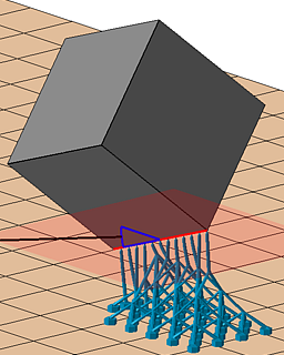
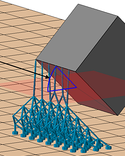
Builds a scaffolding under and around the part and supports it with bars
This is an area-supporting action. It fills the volume underneath supportable surface areas subdivides the determined support into unit cells which are then filled with lattice topology. From the scaffolding thus created, individual bars support the respective downskin clusters. If possible, and enabled, whole groups of eight cells (2×2×2) are collapsed into single cells.
Jump to:
Main parameters
| Parameter | Description | Notes |
|---|---|---|
| Cluster |
See Cluster detection reference |
|
| Anchors |
See Anchors section below |
Anchors |
| Cell width and Cell height |
Determines the size of the smallest cell, and indirectly the angle of diagonal support bars. You should keep the ratio of width to height above a certain value so as to keep the diagonal bars printable. |
|
| Adaptive steps |
The rule of collapsing multiple fully intact lattice cells into the next larger cell size is applied up to this many times. Note that this is only the permissible maximum. If there aren't enough intact cells in a contiguous 2×2×2 arrangement, no collapsing is performed. |
 Comparison of adaptation. Three adaptive steps lighten the lattice considerably more than just one step. |
| Distance part to lattice |
This minimum distance is enforced between lattice and part surface when hugging the surface contours with the lattice scaffolding. |
|
| Lattice go around the part |
If enabled, an additional layer of lattice cells beyond the part circumference is generated to fill even more volume with rigid support but consequently consumes significantly more buildspace on the platform. This helps with supporting part sections otherwise too far up, or significantly undercut by part structures further down. |
|
 Gap between part and lattice
|
Artificially increases the gap between lattice grid and part surface to prevent intersection even on intricate side walls |
|
|
Lattice behavior
|
Controls the expansion and use of additional lattice cells beyond the originally determined volume.
|
|
|
Allow lattice on upskin and sidewalls
|
Permit lattice generation in open or closed cavities where it could not normally grow into and where only regular bars would be generated. |
|
| Single down point tips |
With this switch, this support action can also see to supporting downward-facing protrusions whose sides do not qualify for cluster detection such as when they are steeper than the critical and non-critical angles. This is off by default. |
|
| Support properties |
See Bar Supports reference |
Anchors
| Anchor distance |
Defines the space between two anchor points or bars on the cluster surface. This is independent from the lattice cell size. |
|
| Anchor alignment |
Switches between rectangular and hexagonal anchor placement on the cluster surface. This is independent from the lattice cell topology which has always a quadratic cross section. |
|
| Contour offset to wall |
Anchors keep a distance from a cluster contour that borders a wall (a concave border). |
|
| Free contour offset |
Anchors keep a distance from a cluster contour that does not border a wall. |
|
| Add bars to medial axis |
Traces the centerline of narrow cluster passages to ensure good support in places where neither the regular, area-filling pattern, nor the contour-tracing pattern would fit. |
|
| Medial axis contour offset |
Narrow passages may be at most twice this wide to still receive the medial axis supports. |
|
| Z-range limitation | ||
| Minimal z value, Maximal z value | ||
| Sharp edges |
Toggle to support down-facing edges with a line of additional bar supports each |
|
| Maximum edge angle to XY plane |
Specify a threshold angle from the horizontal for the sides of an edge from which it becomes eligible to receive support |
|
| Neighbor area angle |
Specify a "critical angle" for the surface that itself is not critical but terminates in the sharp edge. |
|