Introduction
Automotive mufflers for on-road applications are subject to road load vibration. Testing in actual conditions, however, is time consuming and expensive. Simulation is an effective tool for exploring a product's response to published road vibration loading. It is a critical part of the design process for evaluating design variations and for identifying a final design candidate that warrants physical testing.
In this exercise, we will set up a normal modes (modal) analysis. We will compare the modes to known road excitation per MIL-STD-810G. In subsequent exercises, we will make design improvements to reduce sensitivity to frequencies of higher energy.
1. Open the Model and Start the Autodesk Inventor Nastran Environment
Start Autodesk Inventor, and open Muffler&Brackets.iam from the Section 22 - Muffler sub-folder of your training exercises folder. (Get Started > Launch > Open)
From the ribbon, click Environments, and Autodesk Inventor Nastran.
You should see this:

- In the Analysis tree, right-click .
- In the Analysis dialog, click the Model State tab.
- Change Level of Detail to Two Brackets.
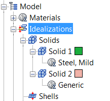
In the Model tree, expand Idealizations. If any Idealizations are already defined, like Solids 1 and 2 below, right-click , to ensure that no unwanted materials can participate in the analysis.
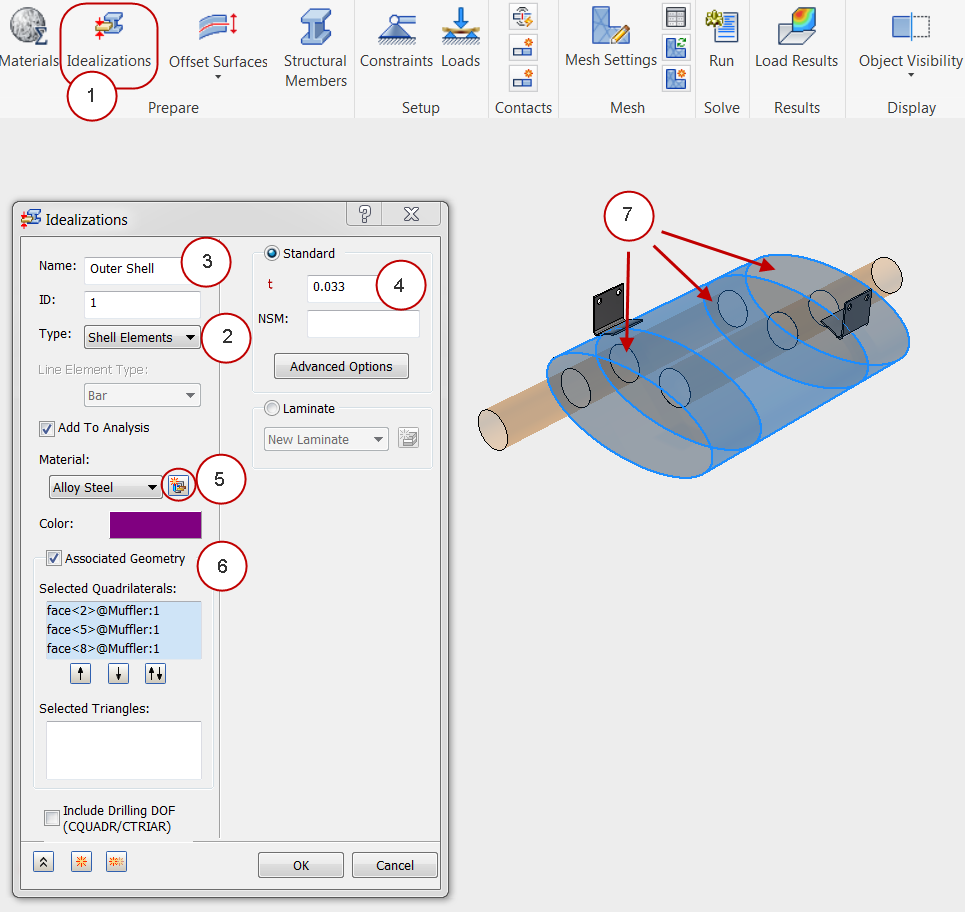
2. Define the Physical Properties
- Click Idealizations from the ribbon.
- Set the Type to Shell Elements.
- Change the Name to Outer Shell.
- Specify a thickness, t, of 0.033.
- Click the New Material icon. On the Material dialog, click Select Material. Expand the Inventor Material Library, and select Alloy Steel. Click OK and OK to close both Material dialogs.
- Check the Associated Geometry box.
- Select the three surfaces that make up the outer muffler shell.
- Instead of closing the dialog, we will duplicate the settings to define the next physical property. Click the Create Duplicate icon.
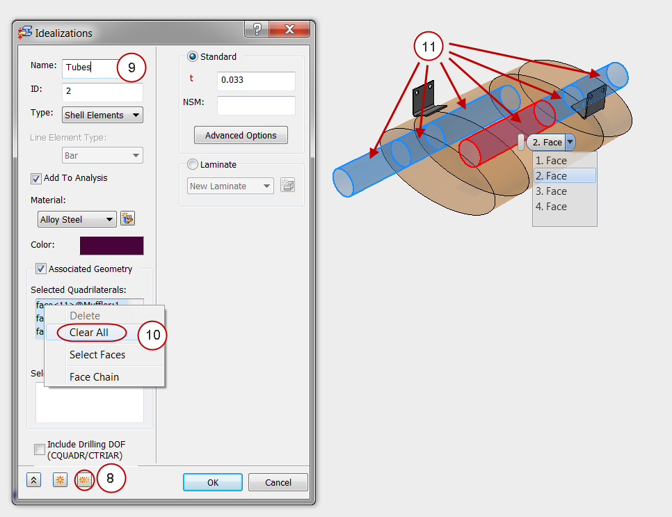
- Change the Name to Tubes.
- Right-click in the Selected Quadrilaterals list, and click Clear All.
- Select the six cylindrical surfaces that make up the tubes. (You may have to hover over the surface and expand the menu to select the correct surface from the list.)
- Click the Create Duplicate icon again.
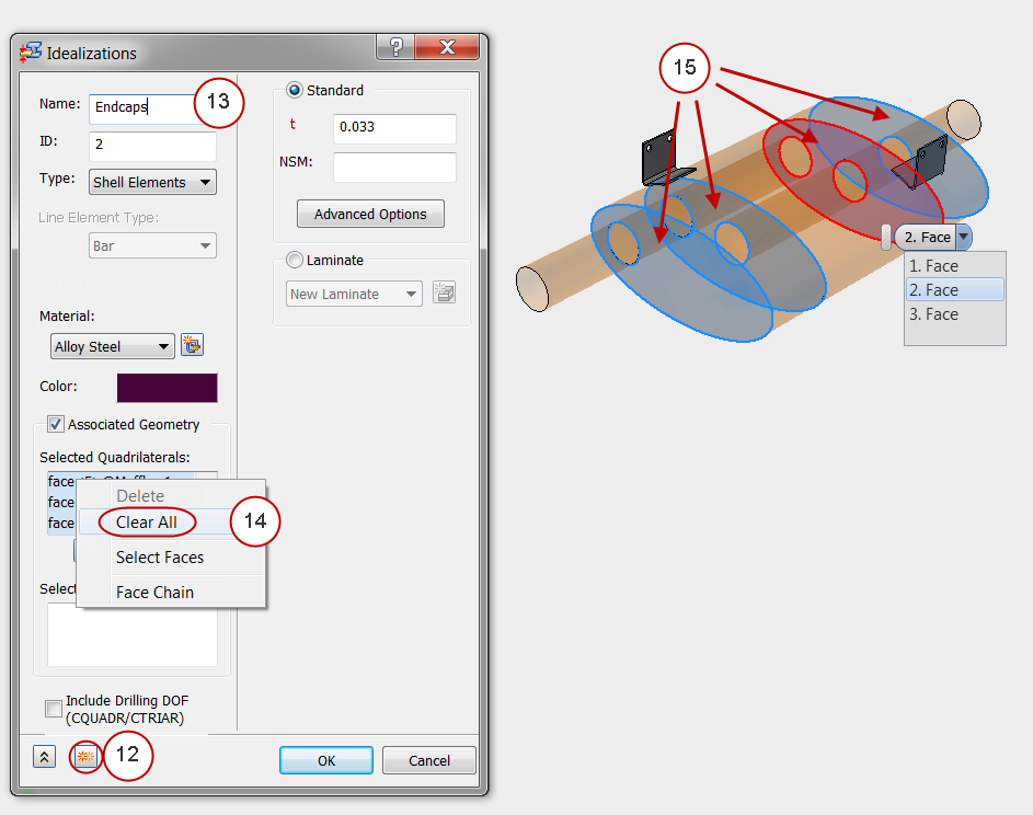
- Change the Name to Endcaps.
- Right-click in the Selected Quadrilaterals list, and click Clear All.
- Select the four planar surfaces that make up the end caps and bulkheads. (You may have to hover over the surface and expand the menu to select the correct surface from the list.)
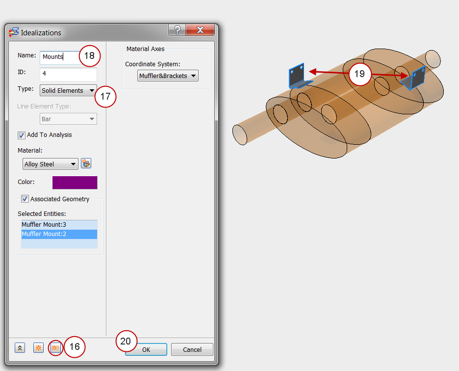
- Click the Create Duplicate icon again.
- Set the Type to Solid Elements.
- Change the Name to Mounts.
- Select the two mounting brackets.
- Click OK.
To check your work, you should see four properties listed in the Assembly tree:

3. Change the Analysis Type
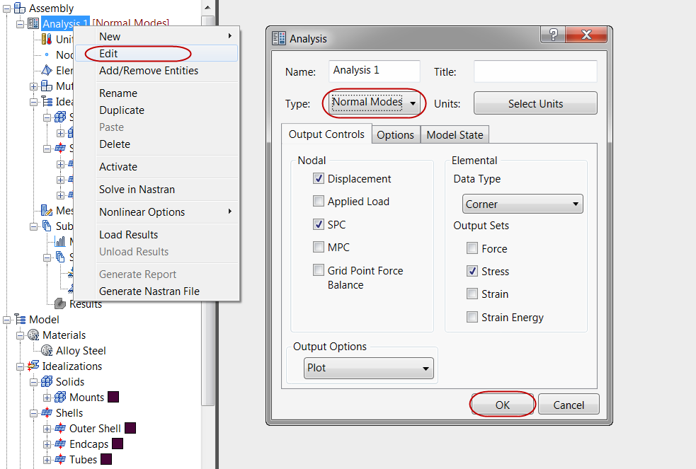
- Right-click Analysis 1 from the Assembly tree, and click Edit.
- Set the Type to Normal Modes, and click OK.
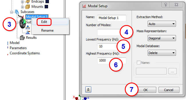
- From the Assembly tree, right-click on Modal Setup 1, and click Edit.
- Delete 10 as the Number of Modes.
- Set the Lowest Frequency to 10.
- Set the Highest Frequency to 1000.
- Click OK.
4. Constrain the Brackets
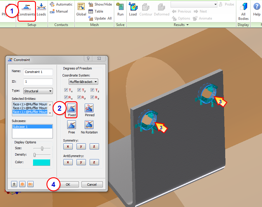
- Click Constraints from the ribbon.
- Make sure Fixed is selected.
- Select the two circular surfaces on each bracket. There should be four surfaces total.
- Click OK.
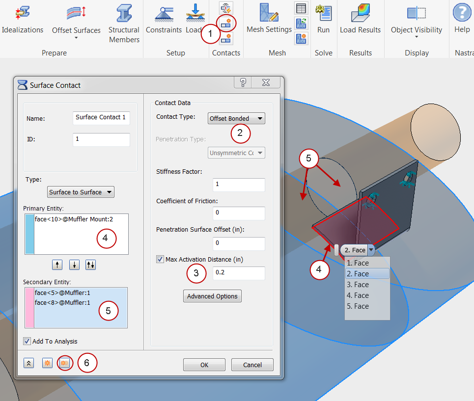
5. Define Contacts
We'll use an Offset Bond contact between the brackets and the muffler shell to ensure that parts that don't touch are bonded together.
- Click Manual from the Contacts panel in the ribbon.
- Set the Contact Type to Offset Bonded.
- Specify a Max Activation Distance of 0.2
- Click in the Primary Entity field, and select the bottom face of the bracket. (You may have to hover over the surface and select the appropriate surface from the list.)
- Click in the Secondary Entity field, and select the two adjacent faces of the muffler that contact the bracket.
- To define the contact for the second bracket, click Create Duplicate. The first contact is added to the Analysis tree.
- Right-click in the Primary Entity field, and click Clear All. Select the bottom face of the second bracket.
- Right-click in the Secondary Entity field, and click Clear All. Select the two adjacent faces of the muffler.
- After the second surface contact is created, click OK.
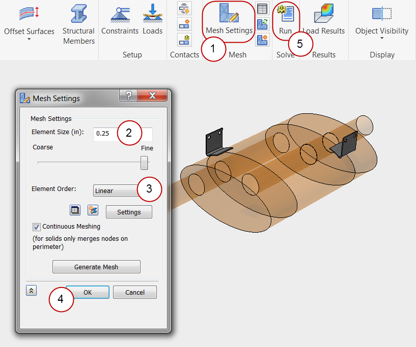
6. Mesh the Model and Run the Analysis
- Click Mesh Settings from the ribbon.
- Set the Element Size to 0.25.
- Set the Element Order to Linear.
- Click OK to generate the mesh and close the dialog.
- Click Run from the ribbon to start the analysis.
7. Review the Frequencies
- Click Result Options from the ribbon, or in the Analysis tree, right-click .
- Open the Subcases menu. The frequencies for each mode are listed:
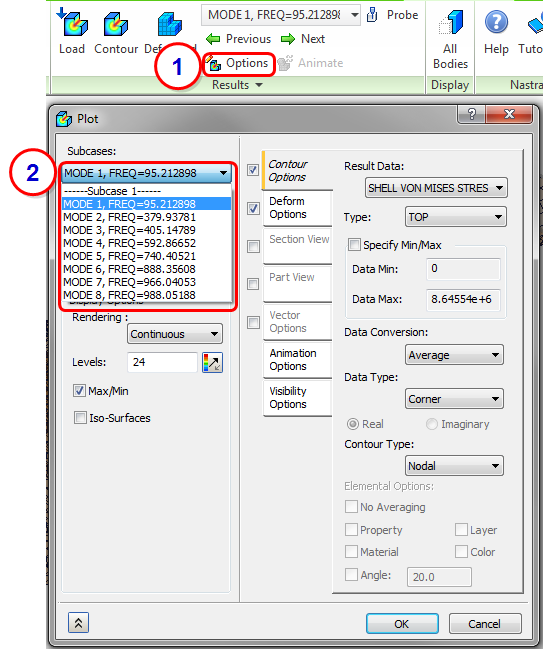
If we overlay these frequencies on the plot from MIL-STD-810G, we can identify the modes to check:
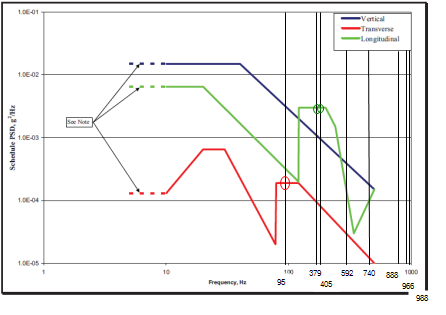
|
Vertical |
Transverse |
Longitudinal |
|
|---|---|---|---|
|
95 |
no |
yes |
no |
|
379 |
no |
no |
yes |
|
405 |
no |
no |
yes |
8. Review the Mode Shapes at Each Frequency
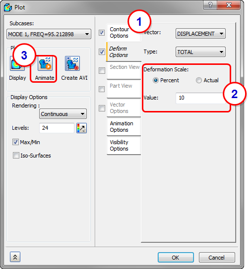
- On the Contour Options tab, select Displacement as the Result.
- Click the Deform Options tab, and set the Deformation Scale to 10%.
- Click Animate, and examine the model to understand the deformation.
- Repeat this for each mode shape.
- To stop the animation at any time, in the Analysis tree, right-click Results and deselect Animate.
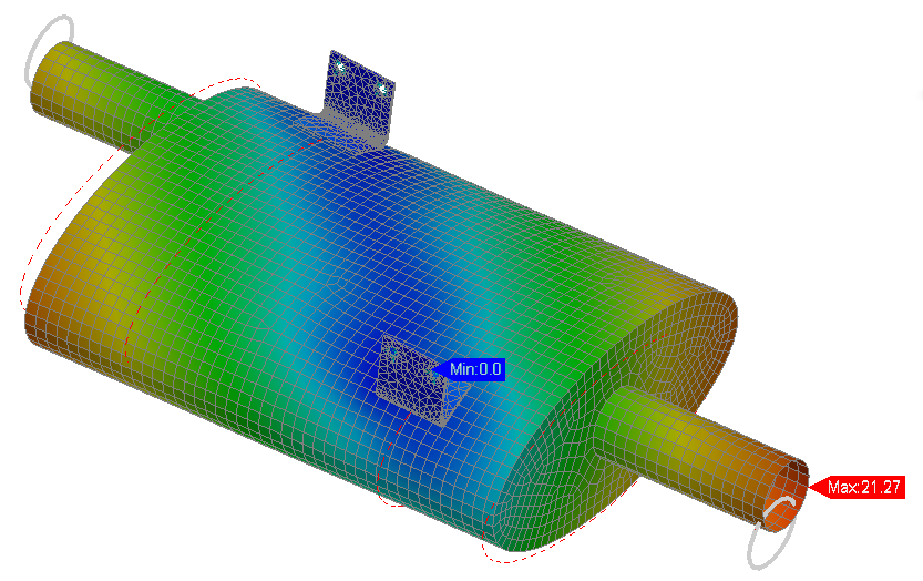
- MODE 1: High input energy in the transverse direction. The rotational mode about the brackets is mostly vertical, but could be excited multi-axially.
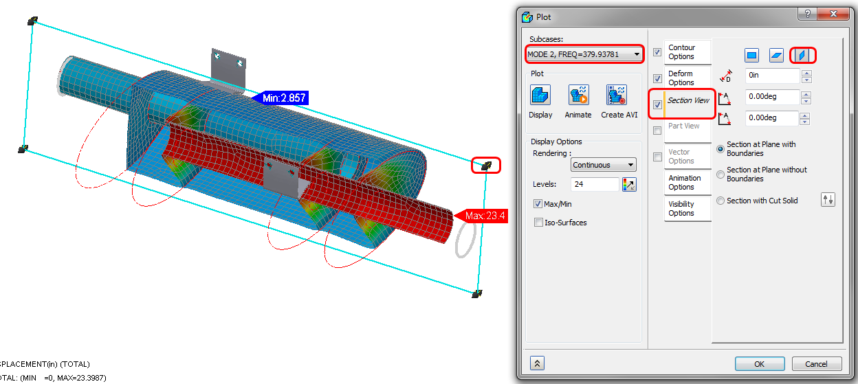
- MODE 2: High input energy in longitudinal direction. The oil-canning of end plates and bulkheads are clearly in jeopardy from the longitudinal vibration. To use a section view, check the Section View tab, and choose the orientation. Drag the section plane using the handles.
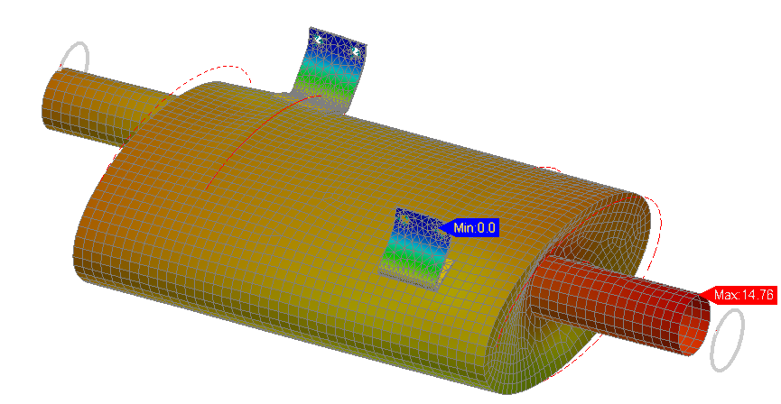
- MODE 3: High input energy in longitudinal direction. This mode is a combination of transverse and longitudinal deformation. There is increased risk of failure due to high longitudinal energy.
Summary
In this exercise, we set up and ran a modal analysis. To help us do this, we assigned shell element properties to surfaces features in the CAD model. This is often an easier method than reducing a solid model to midsurfaces. Additionally, we explored mixed meshing of solid and shell elements, and defined the Offset Bond contact type to ensure that parts that weren't touching bond together. Finally, we explored the post-processing options for modal results, including section views.
|
Previous Topic: Modal or Natural Frequency Analysis |
Next Topic: Modal Avoidance Exercise |