Introduction
In this exercise, we will simulate a simple cantilevered beam with a fixed end and a load applied to the other end. Here is the basic process:
- Open the model of the beam in Autodesk Inventor.
- Apply a property, constraints, and a load.
- Mesh and run the simulation.
- Review the displacement and stress results, and compare to the expected result.
These are the assumptions we will use for this simulation:
- The displacement is small.
- The material exhibits a linear stress-strain response.
- The applied load does not change in magnitude, orientation, or distribution.
- The effects of gravity are negligible.
1. Open the Model
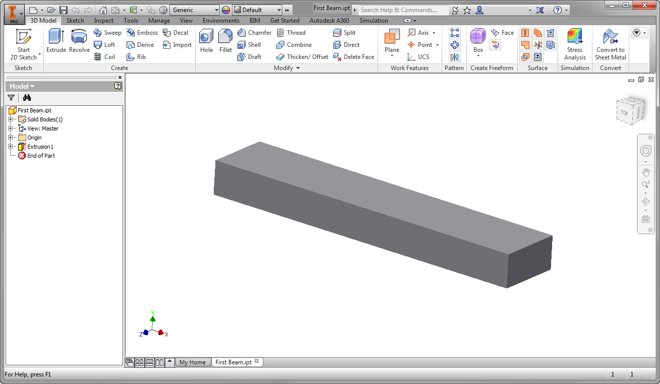
Start Autodesk Inventor, and open First Beam.ipt from the Section 3 - Cantilevered Beam sub-folder of your training exercises folder. You should see this, although the Model pane on the left might not be visible:
2. Start the Autodesk Inventor Nastran Environment
- From the ribbon, click the Environments tab.
- Click Autodesk Inventor Nastran.

3. Assign the Physical Property
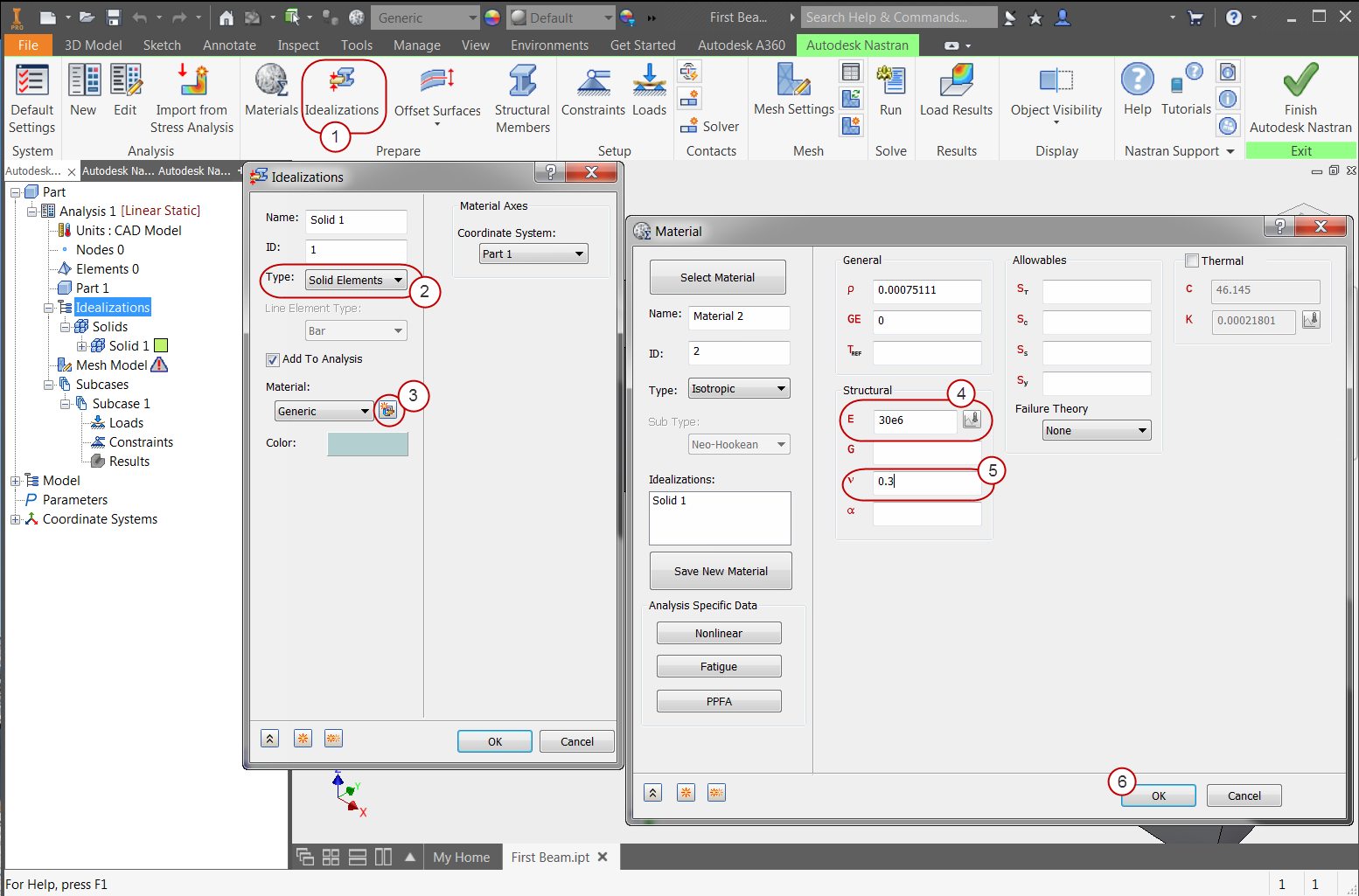
- Click Idealizations from the ribbon.
- On the Idealizations dialog, confirm the Type is Solid Elements.
- Click the New Material icon.
- On the Material dialog, enter 30e6 for E (Young's Modulus).
- Enter 0.3 for v (Poisson Ratio).
- Click OK on the Material dialog.
- Click OK on the Idealizations dialog.
4. Constrain the Beam
In this step, we assign the condition that fixes the beam on one end, preventing movement in any direction.
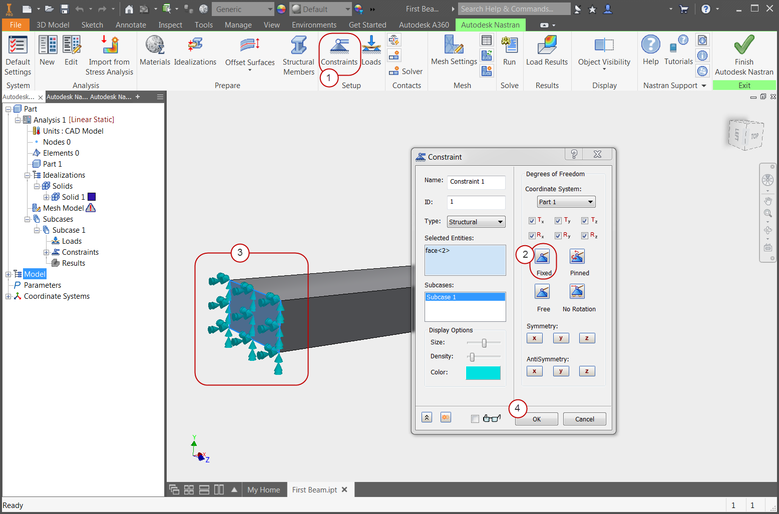
- Click Constraints from the ribbon. Click and move the View Cube in the upper right of the Inventor window to reposition the beam so you have a clear view of one end.
- On the Constraint dialog, click Fixed. (This is the default setting.) Under Display Options, you can also use the Density setting to control the number of constraint symbols that will appear in the image.
- Click the end of the beam, as shown in the image.
- Click OK.
5. Load the Beam
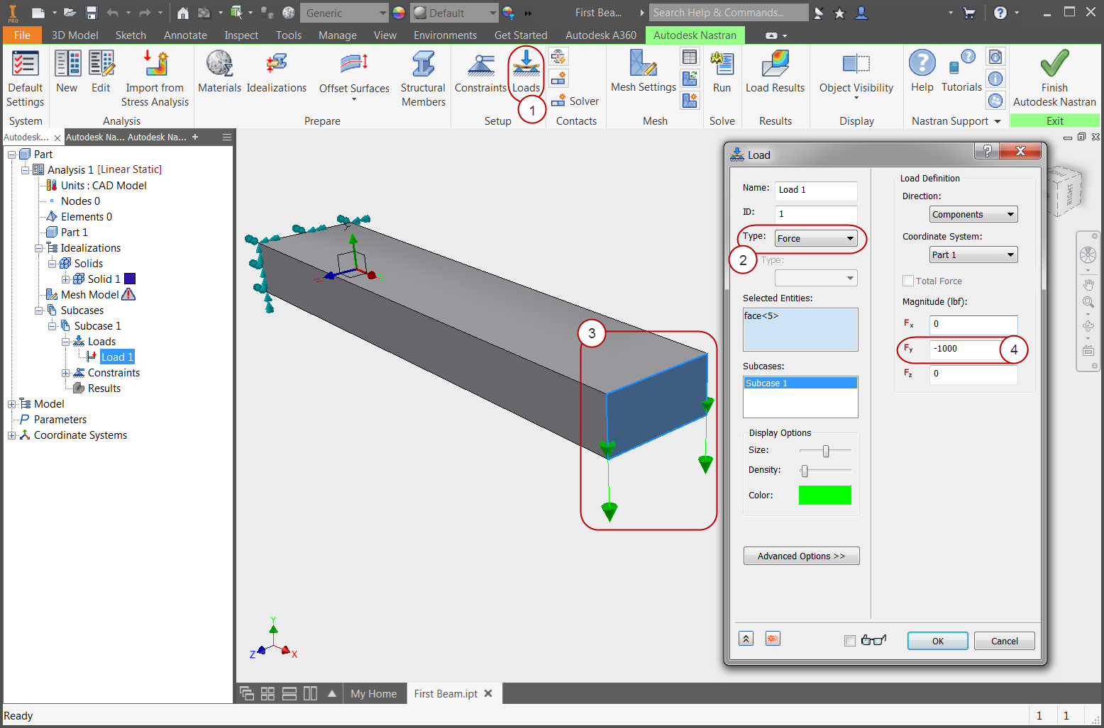
- Click Loads from the ribbon.
- Note that Force is the default Type of load.
- Select the end of the beam that does not have the constraint (as shown).
- Enter -1000 for Fy.
- Click OK.
6. Mesh the Beam
- Click Generate Mesh from the ribbon.
The mesh generates:
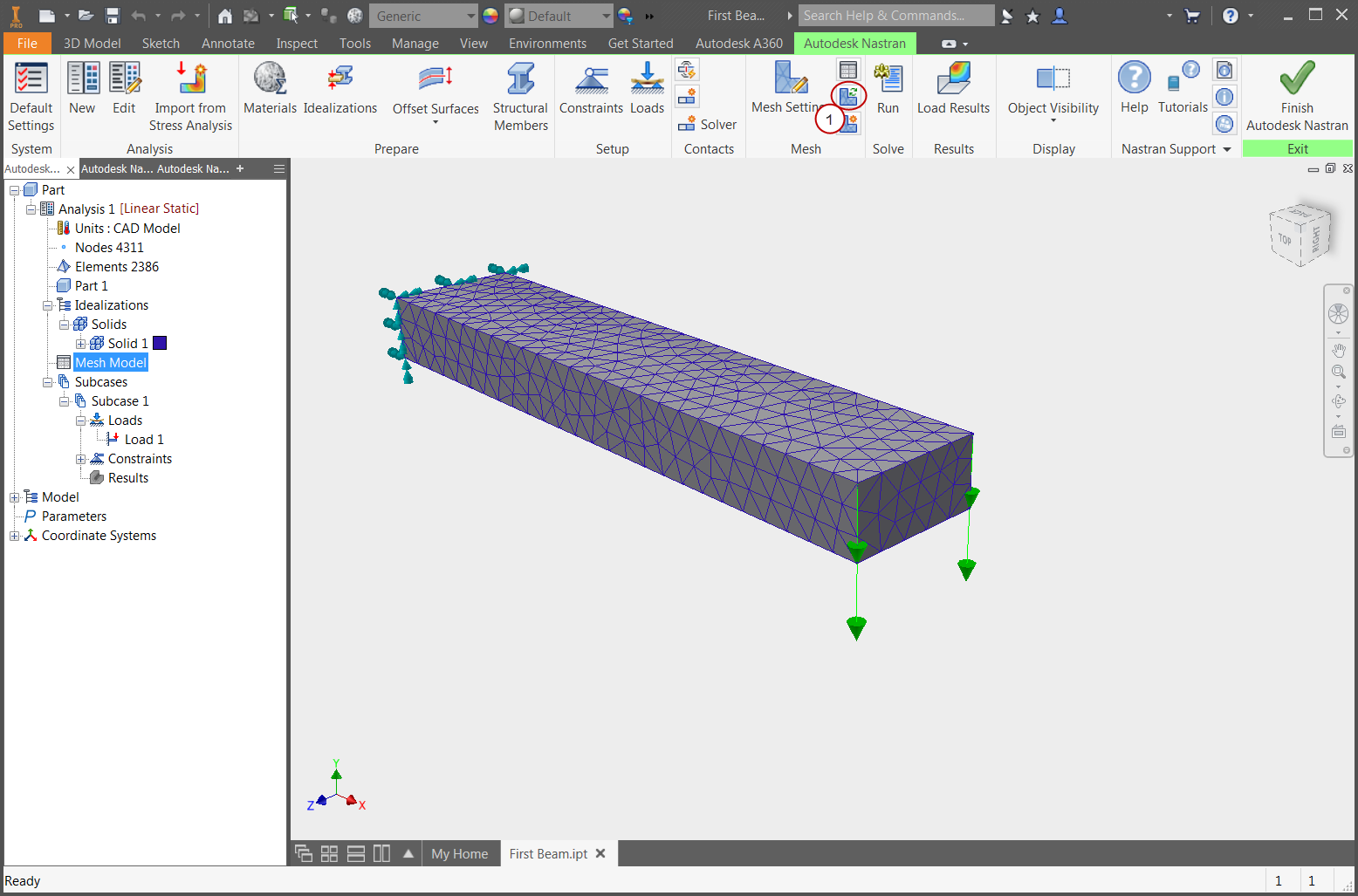
7. Run the Simulation
- Click Run from the ribbon.
- The tree automatically switches to the Autodesk Nastran output. This is a log of the solution progress.
- When the solution is complete, click OK.
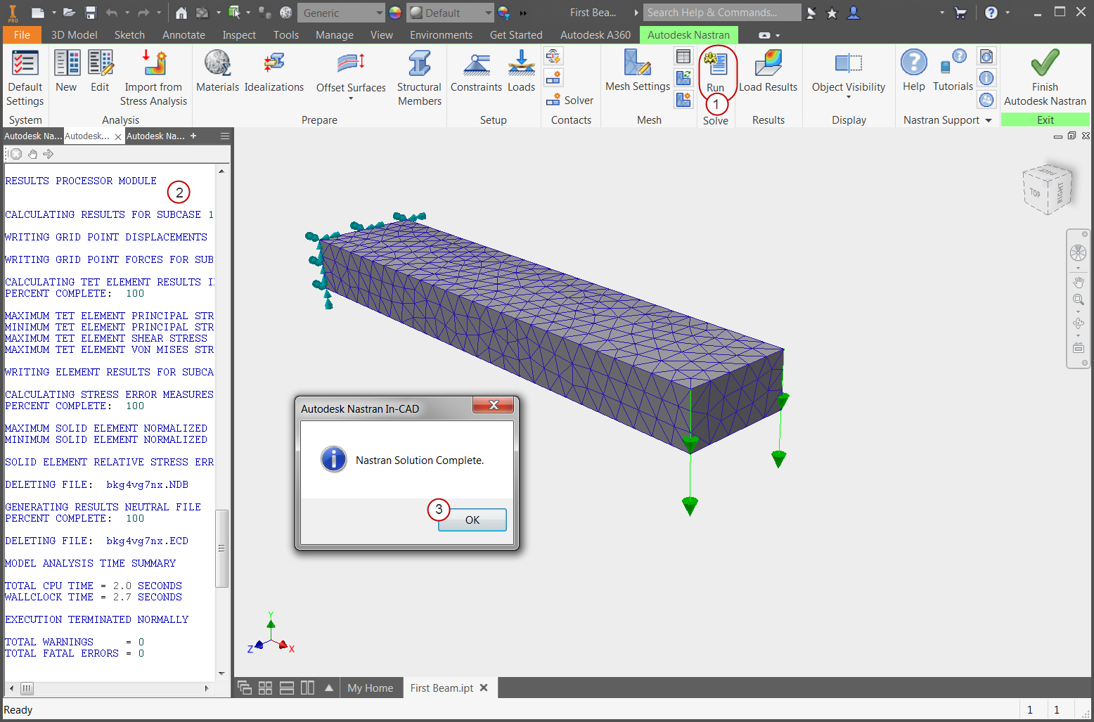
8. Visualize Displacement
- If the Analysis tree is not visible, click on the Autodesk Nastran Model Tree tab.
- Under the Results node of the tree, right-click .
Note the maximum displacement of 0.066 inches.
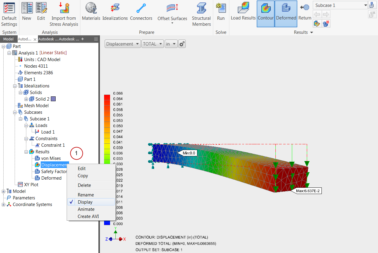
9. Visualize Stress
- Under the Results node of the tree, right-click .
- Note the maximum stress of 29,000 psi.
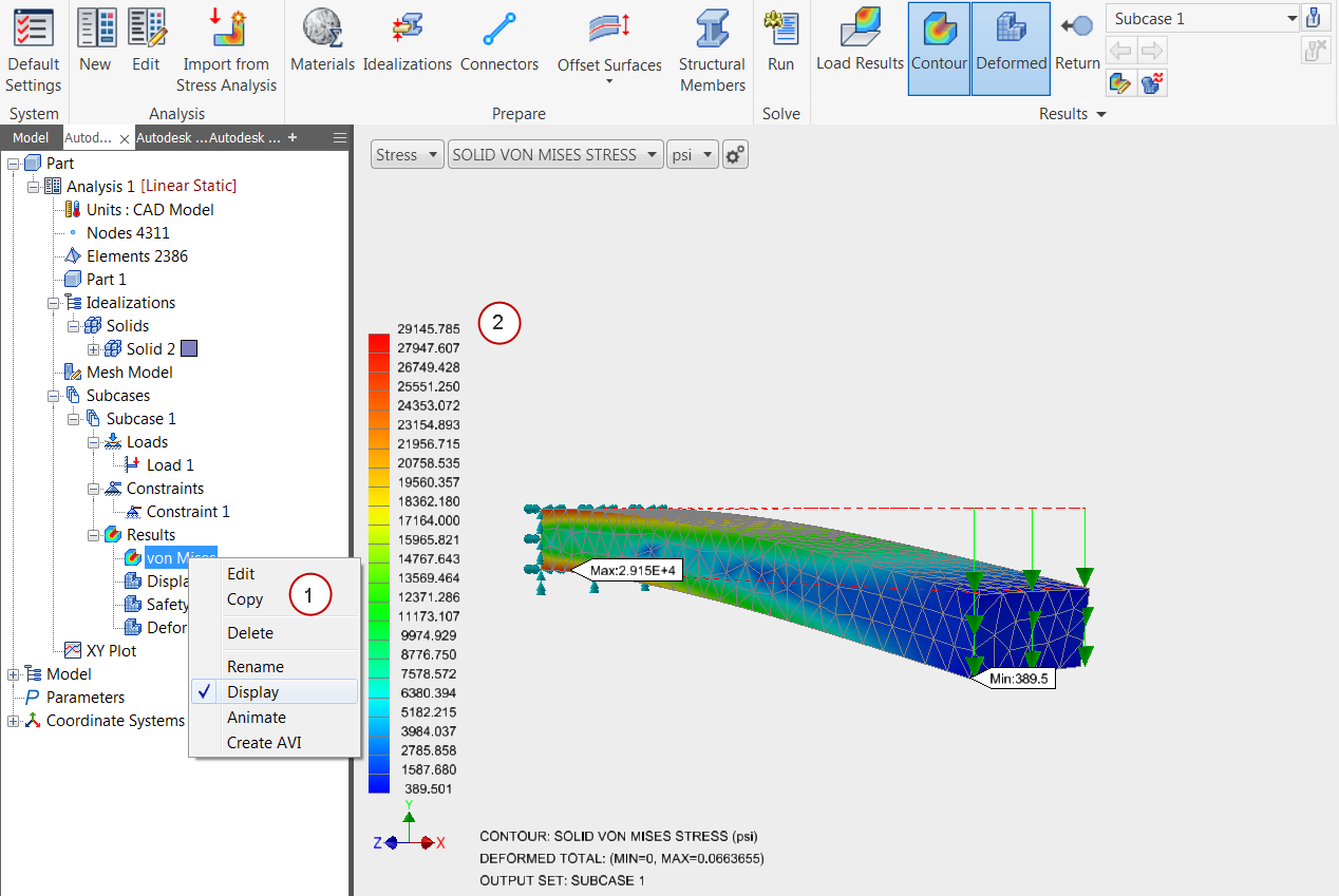
Summary
Congratulations! You have finished your first FEA model in Autodesk Inventor Nastran!
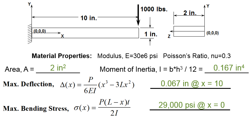
When we compute the response by hand, we find the following:
|
Previous Topic: The Basics of Finite Element Analysis (FEA) |
Next Topic: The User Interface |