Use the Ramp Options dialog to specify how the tool ramps into the stock.
To display this dialog, click the Ramp Options button on the Lead In page of the Strategy dialog or the Surfacing Defaults dialog.
Max zig angle — Enter the angle of descent formed as the tool ramps into the block.
Follow — Select an option to control the direction of the ramp.
-
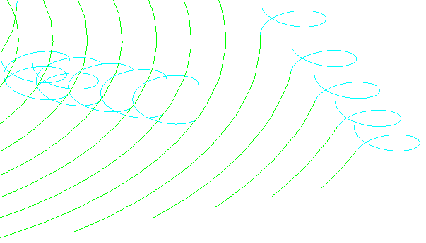
Toolpath — The ramp moves follow the profile of the toolpath.

-
Line — The ramp moves are normal to the cutting direction at that point. If the requested line cannot be fitted into the area, then the
Toolpath option is used automatically.

-
Circle — The ramp moves are circular. If the requested circle cannot be fitted into the area, then the
Line
method is used automatically.
Circle diameter (tool diameter units) — Enter the diameter of the circle using tool diameter units (TDUs).
Ramp height
This is measured with respect to the tool axis. For 3-axis machining, the tool axis is the Z axis. For multi-axis machining, the tool axis is defined on the Tool axis page.
Type — Select how to determine the height from which the ramp descends.
- Incremental — The height above the cleared stock for the start of the ramp.
- Segment — The start of the ramp is at the same height as the end of the previous toolpath segment, provided that this is higher than the toolpath segment by the amount specified in the Height field.
- Segment Incremental — The start of the ramp is at the same height as the end of the previous toolpath segment plus the height specified in the Height field.
Height — Enter the height of the start of the ramp above the option selected in the Type field.