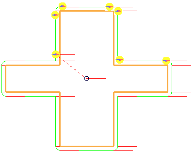
Orientation vector steers the tool by aligning the vector in a particular orientation. The contact track of the tool remains unchanged, but the contact position on the tool is affected as the tool orientation changes.
The Orientation vector is useful when:
- Machining with an asymmetric machine head.
- Using the C-axis rotation of the machine tool to machine a part which otherwise would not fit within the machine tool limits.
- Controlling the orientation of the end of the arm of a robot.
Orientation vector — Select how to control the orientation of the tool.
These options are easiest to see if you draw the orientation vectors (Toolpath tab > Draw panel > Display > Orientation Normals) and then simulate the toolpath (Simulate from start on the individual toolpath menu).
 shows the tool orientation.
Free — When selected, the orientation vector is not controlled.
Fixed direction — When selected, the orientation vector always points in the same direction.

Direction of travel — When selected, the orientation of the vector is determined by the direction of travel.

Offset angle — Enter the orientation angle of the vector. Use this to orient the machine head correctly.
These options are easiest to see if you draw the orientation vectors (Toolpath tab > Draw panel > Display > Orientation Normals) and then simulate the toolpath (Simulate from start on the individual toolpath menu).
 shows the tool orientation.
Offset angle — 0

Offset angle — 30

Direction — Determines the vector of the line. The orientation vector is always perpendicular to the tool axis. When you have a non-vertical tool axis, the only way to specify the direction accurately is to specify the Azimuth and Elevation angles. This option is available only if you have an Orientation vector of Fixed direction.
Azimuth — Enter the angle of the line in the XY plane. The rotation is measured counter-clockwise about the Z axis with 0 at the X axis.

Elevation — Enter the angle of the line relative to the vertical (Z).

Components — Enter values in the fields to edit the machine axis direction by defining a vector with i, j and k components.
 — Click to display the
Direction dialog, which provides further options to edit orientation vectors.
Smooth orientation vectors — When selected, avoids sharp changes in the tool orientation. This option is available only if you have an Orientation vector of Direction of travel.
Maximum angular correction — Enter the maximum angle the smoothed orientation vector may deviate from the original.
Smoothing distance — Smooths the tool orientation over the specified distance. When you get sudden changes in direction in the original toolpath (such as a right angled corner) you get rapid changes of orientation of the tool which leaves dwell marks. To prevent this, the Smoothing distance blends the change in orientation and gives much improved surface finish. This option is only available if you have an Orientation vector of Direction of travel.
These options are easiest to see if you draw the orientation vectors (Toolpath tab > Draw panel > Display > Orientation Normals) and then simulate the toolpath (Simulate from start on the individual toolpath menu).
 shows the tool orientation.
Smooth orientation vectors — Deselected:

Smooth orientation vectors— Selected
Smoothing Distance — 5:
