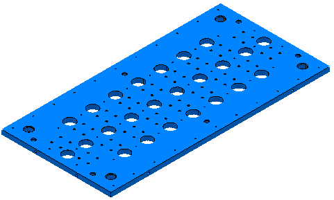
This example shows how to edit holes generated automatically from the Create Holes option. It uses the RetainerPlate.dgk model in the Examples folder.
- Select part of the model, including some of the holes.
- From the
Hole Feature Sets context menu, select
Create Holes.
This displays the Create Holes dialog.
- On the
Create Holes dialog:
- Select a Create from of Model.
- Select Create compound holes.
- Deselect Group holes by axis.
- Select Edit after creation.
- Click Apply.
PowerMill recognises the selected holes.

 Standard holes with the Z axis of the hole aligned with the workplane Z axis.
 Compound holes with the Z axis of the hole aligned with the workplane Z axis.
 Standard holes with the Z axis of the hole not aligned with the workplane Z axis.
- Select the hole you want to edit.

You can also edit holes graphically.
- On the
Edit Holes dialog, edit the required fields, in this case, the
Upper Diameter, and
X and
Y
coordinates.
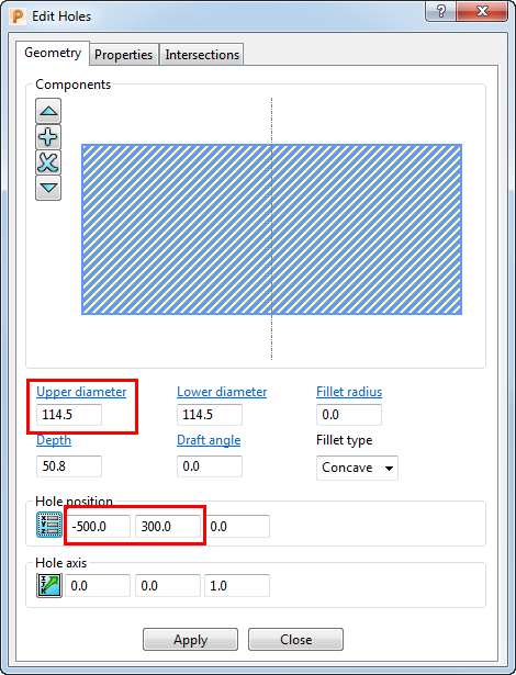
Altering the Upper Diameter automatically updates the Lower Diameter.
If you edit a compound hole, select the relevant component in the graphical area of the dialog (the selected component is cross-hatched), and then edit the appropriate values.
When you select a hole where the Z axis of the hole is not aligned with the workplane Z axis, the
Hole position
coordinates are shown relative to the active workplane rather than the workplane of the hole. In this case
 is added to the dialog. Hovering over
displays more information.
is added to the dialog. Hovering over
displays more information.