The Geometry tab on the Edit Hole dialog edits a component of a hole.
This tab contains the following:
 Move Up — Click to move the selected component up one position.
 Add component — Click to add a component. The new component is the same size as the selected component. You can then edit its size in the lower half of the dialog.
 Delete Selected — Click to delete the selected component.
 Move Down — Click to move the selected component down one position.
The graphic displays the hole you are editing. For compound holes, the currently editable component is cross-hatched blue. To edit a different component, select it in the graphics pane.

You can use the keyboard arrows (
 ) to select the relevant component which can be useful when selecting small components.
If you select multiple holes that are the same size and have the same components, you can edit them all together. If you select multiple holes that differ, the differing components are grey. However, you can still move them and edit the values in the lower part of the dialog:

Where the selected holes have the same value, the value is displayed (for example Draft angle).
Where the selected holes have differing values, the field is empty (for example Upper diameter).
Upper diameter — Enter the diameter at the top of the current (cross-hatched component. This must be greater than or equal to the Lower Diameter.
Depth — Enter the vertical height of the component.
Lower diameter — Enter the diameter at the bottom of the current (cross-hatched) component. This must be less than or equal to the Upper Diameter.
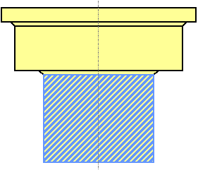
Draft angle — Enter the draft angle of the hole. A value of 0 gives a straight hole with no draft angle.
Draft angle of 0:
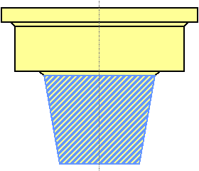
Draft angle of 10:
Fillet radius — Enter the radius.
A Fillet radius of 0 gives a standard hole component with no fillet:

Entering a Fillet radius gives:

The minimum fillet radius has a diameter equal to the length ( ) of the hole component. The length of the component is the same as the Depth for a hole with no draft angle.

The diameter of the fillet must be at least as large as the length of the component.
Fillet type — Select either a Concave or Convex fillet.
Fillet type of Concave:
Fillet type of Convex:

Hole position — Enter the x, y, z coordinates of the centre of the hole.
 — Click to display the Position dialog. Use the dialog to manually enter coordinates and locate items in the graphics window.
Hole axis — Enter the orientation of the Z axis of the hole.
 — Click to display the Direction dialog, which enables you to edit the direction of an item.
 — When displayed, hover over to see more information.
For an example on using this dialog, see Editing automatically identified holes.