Use the Line projection finishing page to project a cylindrical pattern onto the model. The centre of this cylinder is the focus of the pattern and is defined by the Azimuth and Elevation sliders. The range of the pattern is described in terms of height and angular limits.
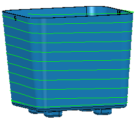
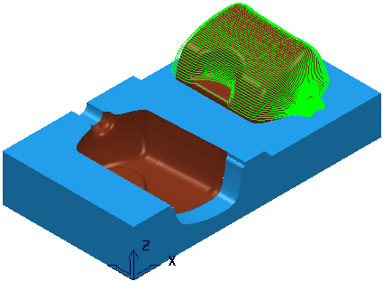
This allows projection to/from a non-vertical (typically horizontal) line. Imagine machining a half-cylinder lying on a plane. Project Inwards for a male cylinder, Outwards for a female. An
Elevation
angle of
90 makes the projection line horizontal and produces toolpath segments along the length of the cylinder.
-
Style — Select a style to define the shape of the pattern.
-
Linear — This produces a line pattern.

-
Circular — This produces a circular pattern.

-
Spiral — This technique produces a spiral pattern. Selecting this option changes the options available on the
Pattern page.
-
Linear — This produces a line pattern.
- Location — Enter X, Y, Z coordinates to determine the start of the line.
-
 — Click to display the
Position dialog. Use the dialog to manually enter coordinates and locate items in the graphics window.
— Click to display the
Position dialog. Use the dialog to manually enter coordinates and locate items in the graphics window.
-
Azimuth — Enter the angle of the line in the XY plane. The rotation is measured counter-clockwise about the Z axis with 0 at the X axis.
-
0 is along the X axis
 Note: Select Draw to see the construction lines.
 -
90 is along the Y axis
 Note: This is the required orientation for this model.
 -
180 is along the -X axis.

-
0
-
Elevation — Enter the angle of the line relative to the vertical (Z).
-
0 is vertical (down the Z axis).
Note: Select Draw to see the construction lines.
-
90 is horizontal (in the XY plane).
Note: This is the required orientation for this model.
Note: Select Draw to see the construction lines. -
0
-
Direction —Select the direction to determine which regions are machined.
-
Inwards
— When selected machines cores. Produces toolpaths on external (visible) surfaces. Typically the axis is inside the part.
-
Outwards
— When selected machines internal fillets, holes or cavities. Typically the axis is outside the part.

-
Inwards
— When selected machines cores. Produces toolpaths on external (visible) surfaces. Typically the axis is inside the part.
- Tolerance — Enter a value to determine how accurately the toolpath follows the contours of the model.
- Thickness — Enter the amount of material to be left on the part.
-
 Component thickness — Click to display the
Component thickness dialog, which enables you to specify the thicknesses of the different surfaces.
Component thickness — Click to display the
Component thickness dialog, which enables you to specify the thicknesses of the different surfaces.
-
Stepover —Enter the distance between successive machining passes.
Note: This option is available only if you have a Style of Circular or Spiral.
-
Angular stepover —Enter the angle between consecutive passes.
Note: This option is available only if you have a Style of Linear.
- Preview — Click to produce a quick preview toolpath over the projection shape.
- Draw — Select to display the preview pattern.