Use the Disc profile finishing page to create a profile toolpath using a tipped disc tool. The edge of the tool, rather than the tool tip is driven along the surface. This strategy will not cut at sharp angles, but will retract, re-position and then plunge before continuing machining.
Drive curve — Select for an embedded pattern to determine the machining profile. This enables you to profile a specific part of the model, rather than all of it. If no embedded pattern is selected, the selected surface determines the machining profile.
 Create pattern — Click to create a new empty pattern.
 Selected pattern — Select a pattern from the list. If no pattern is displayed, or
 is selected, then no pattern is selected. The list contains a list of all available patterns.
 Select picked pattern — Click to select a pattern by picking in the graphics window, rather than by name in the
Select pattern list.
Select picked pattern — Click to select a pattern by picking in the graphics window, rather than by name in the
Select pattern list.
Clicking
displays the
Pick Entity tab. Select a pattern in the graphics window to close the
Pick Entity tab and display the pattern in the
Selected Pattern field.
 Collect curves — Click to copy the selected curves into the pattern. This provides a fast, powerful means of extracting curve geometry from a surface model and copying it into the active pattern/boundary. For more information, see the
collecting curves example.
Collect curves — Click to copy the selected curves into the pattern. This provides a fast, powerful means of extracting curve geometry from a surface model and copying it into the active pattern/boundary. For more information, see the
collecting curves example.
Tool axis
Orientation — Select the tool shank orientation.
Inside:
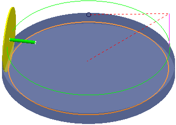
Outside:
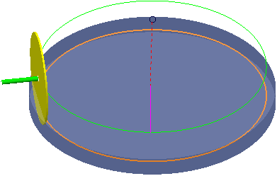
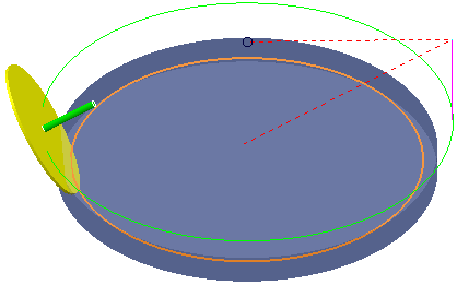
Elevation — Enter the angle of the disc axis, from the horizontal.
An elevation angle of 30
Profile
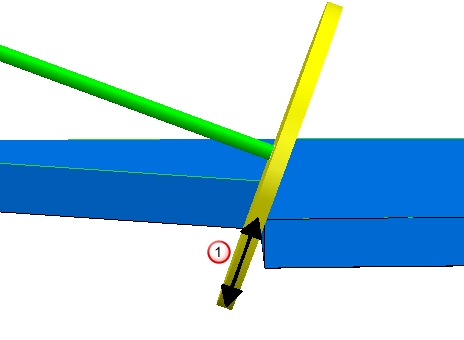
Total depth of cut — Enter the total depth.
The
Depth of Cut,
 , is measured in the plane of the disc. This means that the depth of cut is not necessarily along the Z axis.
Min curvature radius — Enter the minimum machinable curvature radius. When the curvature is sharper than this, the tool will retract, re-position and then plunge before continuing machining, so removing parts of the toolpath.
Tolerance — Enter a value to determine how accurately the toolpath follows the contours of the model.
Cut direction — Select the milling technology.
Select a Cut Direction from the following:
-
Climb — Select to create toolpaths using only climb milling, where possible. The tool is on the left of the machined edge when viewed in the direction of tool travel.

-
Conventional — Select to create toolpaths using only conventional or upcut milling, where possible. The tool is on the right of the machined edge when viewed in the direction of tool travel.

- Any — Select to create toolpaths using both conventional and climb milling. This minimises the tool lifts and tool travel.
Thickness — Enter the amount of material to be left on the part. Click the
Thickness
 button to separate the
Thickness
box in to
Radial thickness
button to separate the
Thickness
box in to
Radial thickness
 Axial thickness
 . Use these to specify separate
Radial and
Axial thickness as independent values. Separate
Radial and
Axial thickness values are useful for orthogonal parts. You can use independent thickness on sloping walled parts, although it is more difficult to predict the results.
. Use these to specify separate
Radial and
Axial thickness as independent values. Separate
Radial and
Axial thickness values are useful for orthogonal parts. You can use independent thickness on sloping walled parts, although it is more difficult to predict the results.
Radial thickness — Enter the radial offset to the tool. When 2.5-axis or 3-axis machining, a positive value leaves material on vertical walls.

Axial thickness — Enter the offset to the tool, in the tool axis direction only. When 2.5-axis or 3-axis machining, a positive value leaves material on horizontal faces.

 Component thickness — Click to display the
Component thickness
dialog, which enables you to specify the thicknesses of the different surfaces.
Component thickness — Click to display the
Component thickness
dialog, which enables you to specify the thicknesses of the different surfaces.