The bottom portion of the NC Program dialog enables you to display and change the settings for each toolpath in the NC program. To display a toolpath's settings, select the toolpath from the Toolpath list.
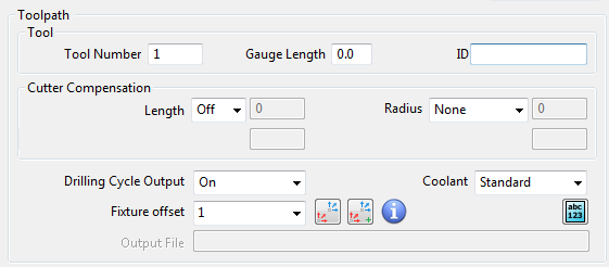
Tool Number — Enter the tool number used by the toolpath. By default this is the same as the Tool Number on the Tip tab of the Tool dialog. This is added to the cut file.
Gauge Length — Enter the gauge length. By default this is the same as the Gauge Length on the Holder tab of the Tool dialog. The value is the total length of the tool assembly that protrudes from the spindle when mounted in the machine tool (the length from the tip of the tool to the top of the holder).
ID — Enter the name of the tool. By default this is the same as the Cutting data tab of the Tool dialog, and is added to the cut file. If you export a tool to a tool database you export the Tool ID and not the Name (on the Tip tab of the Tool dialog). By default the Tool ID is the same as the Name. This is added to the cut file.
Cutter Compensation — For most controls, except the Heidenhain, you need to enter the actual value used for length and radius compensation into the machine tool. To do so, enter the values into a register which is accessed by a number in the NC program.
For example, suppose you require a tool radius offset of 0.2 in the first toolpath and 0.4 in the second toolpath and set the radius offset number to 31 in the first toolpath and 32 in the second toolpath, the NC program file contains the codes G41 ... D31 in the first toolpath and G41 ... D32 in the second. Then type 0.2 into register 31 and 0.4 into register 32 and the values 0.2 and 0.4 will be used for the first and second toolpaths respectively.
Most people use the same number for the length offset number, the radius offset number, and the tool number. For example they expect to see T5, H5, and D5 in the same toolpath. Alternatively the radius offset number may have a fixed connection with the tool number. For example, if the tool number is 5 the radius offset number is 35, if the tool number is 7 the offset is 37. This can be easily taken care of by the postprocessor.
Occasionally however it is not possible to do this, so PowerMill has the ability to change the numbers if this is really required, but the default numbers are usually correct, and the numbers are used only if length or radius compensation is used.
Length — Select the type of cutter length compensation on the machine tool controller. The tool length used in PowerMill remains unchanged.
- Off — When selected, the value 0 appears in the file.
- On — When selected, the default is the tool entity length.
Compensation length — Enter the tool length, by default it is the tool entity length. This enables you to alter the length of the tool in the NC toolpath.
Length Offset Number — Enter the offset register number, used on the machine tool controller, to store length offset value. This is usually the same as the tool number and is useful when the default numbers are not correct.
Radius — Select the type of cutter radius compensation on the machine tool controller. The tool radius used in PowerMill remains unchanged.This enables you to offset a toolpath at the machine controller by an amount stored in a specific offset register.
- None — When selected, there is no radius cutter compensation.
- 2D — When selected, uses 2D cutter compensation which issues a left code.
- Left — When selected, cutter compensation is added by issuing a G41command at the beginning of the tool moves that require compensation.
- Right — When selected, cutter compensation is added by issuing a G42 command at the beginning of the tool moves that require compensation.
- 3D — When selected, writes contact normal vectors for use with 3D cutter compensation. This is essential when the machine tool does the 3D cutter compensation and PowerMill outputs i, j, k vectors in the tape file. To enable 3D Cutter compensation, click Toolpath Edit tab > Edit panel > Point Distribution and then on the Point Distribution dialog, select Contact Normals.
To enable 3D Cutter compensation on all toolpaths select all the toolpaths in the list and then select a Radius of 3D and select the Contact Normals option in the Point Distribution dialog.
It is no longer possible to write normals and left/right codes in the same toolpath. You must adjust any option files which have cutter compensation left/right codes as well as the normals.
Compensation radius — Enter the tool radius, by default it is the tool entity radius. This enables you to alter the radius of the tool in the NC toolpath.
Radius Offset number — Enter the offset register number, used on the machine tool, to store radius offset value. This is usually the same as the tool number and is useful when the default numbers are not correct.
Drilling Cycle Output list — Select Yes to save drilling cycles as canned cycles.
Coolant — Select a coolant option to apply to the selected toolpath.
- None — When selected, there is no coolant output.
- Standard — When selected, turns the coolant on.
- Flood — When selected, turns the coolant to flood.
- Mist — When selected, turns the coolant to mist.
- Tap — When selected, turns the coolant to tap.
- Air — When selected, turns the coolant to air blast.
- Through — When selected, turns the coolant to through spindle.
- Double — When selected, enables two coolant codes.
PowerMill turns the coolant off at the end of a toolpath.
You can apply coolant several different places. For more information see Coolant and how it updates/flows.
Fixture offset list — Select a fixture offset to apply to the selected toolpath. To create or edit a fixture offset, click
 .
.
 Fixture offset for setups — Click to display the Setups in
NC Program dialog. This enables you to apply fixture offsets to setups in an NC Program.
Fixture offset for setups — Click to display the Setups in
NC Program dialog. This enables you to apply fixture offsets to setups in an NC Program.
Fixture offset — Click to display the
Fixture offset for NC Program dialog. This enables you create and edit fixture offsets.
 Add Commands — Click to display the
NC Program Commands/Comments dialog. The dialog enables you to specify commands and comments that are inserted into the NC program.
Add Commands — Click to display the
NC Program Commands/Comments dialog. The dialog enables you to specify commands and comments that are inserted into the NC program.
Output File — Specify the naming convention for the output files. You can enter variables into the filename which are resolved when you write the NC program.