Use the Tip tab to define the geometry of the cutting portion of the tool. With the exception of the form tool and the routing tool, the tab is similar for all the tool types, except for the Geometry area which changes according to the tool you are creating.
To display a Tool dialog:
- Click Home tab > Tool panel > Create Tool; or
- From the Tools context menu, select Create Tool.
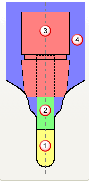
The cutting portion of the tool is yellow, the non-cutting portion green, and the tool holder pink.
Name — Enter the name of the tool.
Geometry — Enter the geometry of the tool.
Tool Status — Check the field to make sure you are creating a valid tool. When you change the tool geometry the status is automatically updated.
Tool Number — Enter the tool number. This is allocated to the tool and added to the cut file.
Number of Flutes — Enter the number of flutes on the tool.
Tool Assembly — This area displays the defined parts of the tool assembly as well as the holder profile.
 tool
tool
 shank
shank
 holder
 holder profile
 — Select a value from the list to zoom in or out of the tool assembly. You can then use the mouse to pan the image.
 — Use the slide bar to zoom in or out of the tool assembly. You can then use the mouse to pan the image.
 Tool Assembly Preview
— Click to display the Tool Assembly Preview dialog. The dialog is useful for looking in detail at large tool assemblies that are too large to be seen effectively in the Tool Assembly pane.
Tool Assembly Preview
— Click to display the Tool Assembly Preview dialog. The dialog is useful for looking in detail at large tool assemblies that are too large to be seen effectively in the Tool Assembly pane.
 Load Tool Assembly — Click to display the Import Tool Assembly dialog. The dialog enables you to load a tool, shank and holder profile that has been created in PowerShape or an alternative CAD program. A tool assembly must have the tool defined in yellow, the shank in green and the holder in pink. This button is available only on the Form tool and the Routing tool dialogs.
 Copy Tool — Click to create a new tool entity based on the current tool. It has the same name as the previous tool with the addition of _1. You can then change any parameters you want without changing the original tool, but you need to bear in mind that, where the original tool is used in an active toolpath, the new tool assembly replaces the original tool assembly. Use this to create a shank and/or holder for an existing tool definition and is useful when collision checking.
 Clear Tool Assembly — Click to delete all items in the tool assembly. This
  is displayed in the Explorer to tell you that the tool is not valid.
 Add Tool to Tool Database — Click to display the
Tool Database Export
dialog. Adding a tool to the Tool Database is useful if you want to reuse the tool in the future.
Add Tool to Tool Database — Click to display the
Tool Database Export
dialog. Adding a tool to the Tool Database is useful if you want to reuse the tool in the future.