The NC Program dialog is available by:
- Clicking NC Program tab > Create panel > Create.
- Clicking NC Program tab > Edit panel > Settings.
- Selecting Settings on an individual NC Program menu.
- Selecting Create NC Program on the NC Programs menu.
This dialog contains the following:
The top portion of the dialog contains information relevant to the NC program as a whole.
Name — Displays the name of the NC program as it appears in the Explorer. If necessary, enter a new name to rename the NC program.
 Options — Click to display the
NC Programs > Output page of the
Options dialog. For more information see
Options > NC Program.
Options — Click to display the
NC Programs > Output page of the
Options dialog. For more information see
Options > NC Program.
Output File — Enter the name and directory of the output file used when writing all the toolpaths in an NC program in one file. The same
variables are available as for
Root Name, except
%[counter] and
%[toolpath]. Select
 to choose an output file.
This option is available only if you have deselected Write File for Each Toolpath on the NC Programs > Output page on the Options dialog.
Machine Option File — The field displays the file path of the selected machine-tool option file (such as Fanuc11m). When
<From Machine Tool> is displayed,
PowerMill uses the
option file associated with the machine tool. Click
to display the
Select Option File dialog and browse for a machine option file.
A number of machine option files are available in the following location: C:\Users\Public\Documents\Autodesk\Manufacturing Post Processor Utility\Generic\.
 Probing options — Click to display the Probing NC Program Options dialog, where you can specify
CAD export and
probe coordinate override settings.
Probing options — Click to display the Probing NC Program Options dialog, where you can specify
CAD export and
probe coordinate override settings.
Machine Tool — Select the machine tool that you will use to machine the part. PowerMill saves the selection and uses the specified machine tool when simulating the machine tool.
Model location — Select the workplane that positions the model in the correct position on the machine tool. This is useful for simulation purposes. The workplane should have the same orientation as the output workplane. PowerMill saves the selection and uses the specified-model-location workplane when simulating the NC program.
If you do not select a machine tool, PowerMill uses the active machine to simulate the NC program.
To simulate the NC program with a different machine tool or model location as an experiment, from the Machine Tool tab, select a different machine tool or model location, and from the Explorer, right-click the NC program and click Simulate from Start. These changes do not change the settings on the NC program dialog.
Output workplane — Select which workplane in the PowerMill project aligns with the machine tool coordinate system. Selecting a workplane specifies the orientation of the part relative to the machine tool. If no output workplane is selected, or implied from the selection on the NC preference dialog, PowerMill uses the output workplane of the first toolpath in the NC program. If the NC program output workplane differs from the output workplane of first toolpath in the NC program, PowerMill issues a warning. The output workplanes specified in the NC program, NC preference, or strategy dialogs don’t have to be the same (just as tool number, coolant, drilling cycles don’t), if they are different, the output workplane selected here is used in preference to the output workplane selected elsewhere.
Program Number — Enter a number to the start of the NC program file. Some controllers require a number at the start to the NC program file.
For example, for the Fanuc controls, the file looks something like this:
%
:1234
N10G91G28X0Y0Z0
N20G40G17G80G49
N30G0G90Z33.031
In this case, 1234 is the program number.
Automatic Tool Alignment — Deselect when the output workplane is different from the toolpath workplane but no angular moves should appear in the NC program file. For example, if you manually turn the head to the required angle.
Part Name — Displays the name of the part which is being cut. If necessary enter a new name. The part name can be used to appear at the beginning of the NC program file (depending on how the tape start is set in the machine option file).
Tool Value — Select whether the output is specified in terms of Tool Tip or Tool Centre. The tool centre is defined as the tool tip offset by the tip radius in the direction of the tool axis.
Connection Moves — Specify how the tool moves from one toolpath to the next. Previously, the tool moved to the new location and then rotated to the required orientation. The option is only available when multi-axis toolpaths are present.

- Move, Rotate — When selected, the tool moves to the new location and then rotates to the correct orientation.
- Rotate, Move — When selected, the tool rotates to the correct orientation and then moves to the new location.
- Simultaneous — When selected, the tool moves and rotates simultaneously. This is the default option.
Toolpath List — Displays all the toolpaths in the NC program, together with the parameters used to create the toolpath. Select one or more of the toolpaths to display information about them in the lower half of the dialog.

You can drag and resize the columns by placing the cursor over the end of a column and dragging it to a new location.
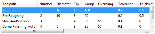
The Number field is the Tool Number.
If the Number is surrounded by brackets, (2) it indicates that there is no tool change for this toolpath.
If the Number is preceded by an asterisk, * it indicates that Tool Number for this toolpath has been edited in the lower portion of this dialog.
If the Number is replaced by a ? it indicates that no tool number has been specified, but a Tool Numbering of As Specified has been selected.
You are not allowed to define the same Number for a tool as one that already exists for a different tool. The only time when this is not the case is when you write a separate file for each toolpath, where all default tool Numbers are 1. The first Tool Number in any file defaults to 1.
 Toolpath List — Click to display the list of toolpaths and their parameters (used in the NC program) in a separate dialog.
 Tool List — Click to display the list of tools and their parameters (used in the NC program) in a separate dialog.
You can right-click on the columns in the Toolpath List and Tool list dialogs to customise the view or copy data to an external application.
Reset — Click to reset the Tool Numbers to their original values. The Tool Number can be edited in the lower portion of the dialog and is displayed in the Toolpath List.
Tool Change — Specify when a Load Tool command is written.
- On Change — Select to add a load tool command at the beginning of the first toolpath and subsequently only if the tool geometry changes. This adds a load tool command if the tool length is different.
- Always — Select to add a load tool command at the beginning of every toolpath even if the tool parameters are the same.
- On New Tool — Select to add a load tool command at the beginning of the first toolpath and subsequently only if the toolpath uses a different tool entity from the previous toolpath.
Tool Numbering — Specify the numbering system used to identify tools in the NC program.
- Automatic — Select to give a new number to each new tool used. When a tool is reused in another toolpath, its existing number is used.
- As Specified — Select to use the tool number specified in the Tool entity dialog. If a tool number has not been specified in any dialog, a ? is displayed in the toolpath list — however, if it is the first toolpath, the tool number is assumed to be 1.
-
Sequential — Select to sequentially name the tools. By default, the first tool is named
1, followed by
2,
3,
4
and so on.
The Tool Number field in the specific toolpath area of the NC program dialog defines the first number in a sequential series.
If the same tool is used in the subsequent toolpath in an NC program, the tool number is enclosed in brackets, for example, (1).
Tool Change Position — Specify whether a tool is changed before or after the connection move.
- After Connection — Select for the tool change to take place after the connection moves. This is the default option.
- Before Connection — Select for the tool change to take place before the connection moves.