Use the Wireframe profile machining page to cut with the side of the tool as it follows the curve. This is similar to wireframe swarf machining and 2D curve profiling.
Surfaces are not required for this strategy, only a 3D curve. To generate a wireframe profile toolpath you must first create a Pattern from the curve.
The Drive curve determines which curve or set of curves is used to create the cutting moves.
 Create pattern — Click to create a new empty pattern.
 Selected pattern — Select a pattern from the list. If no pattern is displayed, or
 is selected, then no pattern is selected. The list contains a list of all available patterns.
 Select picked pattern — Click to select a pattern by picking in the graphics window, rather than by name in the
Select pattern list.
Select picked pattern — Click to select a pattern by picking in the graphics window, rather than by name in the
Select pattern list.
Clicking
displays the
Pick Entity tab. Select a pattern in the graphics window to close the
Pick Entity tab and display the pattern in the
Selected Pattern field.
 Collect curves — Click to copy the selected curves into the pattern. This provides a fast, powerful means of extracting curve geometry from a surface model and copying it into the active pattern/boundary. For more information, see the
collecting curves example.
Collect curves — Click to copy the selected curves into the pattern. This provides a fast, powerful means of extracting curve geometry from a surface model and copying it into the active pattern/boundary. For more information, see the
collecting curves example.
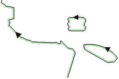
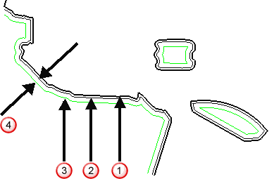
Curve side — Select which side of the pattern you want to machine.
Selecting Left gives:
Selecting the Right gives:
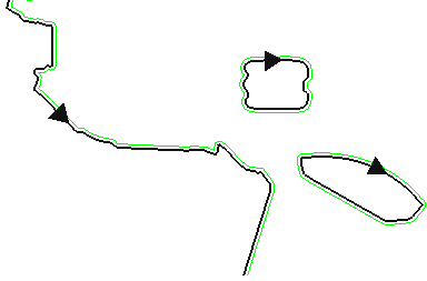
The curve is black and the toolpath green.
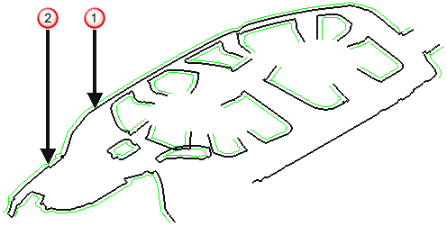
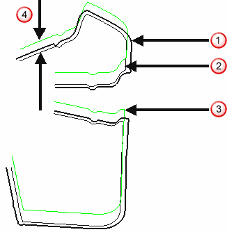
The Lower limit determines the vertical location of the toolpath.
Base position — Select how to determine the lowest position of the toolpath.
-
Curve -
the curve forms the base position of the toolpath.
-
Model -
the model forms the base position of the toolpath.
 Pattern
 Toolpath
 Model, in this case a plane.
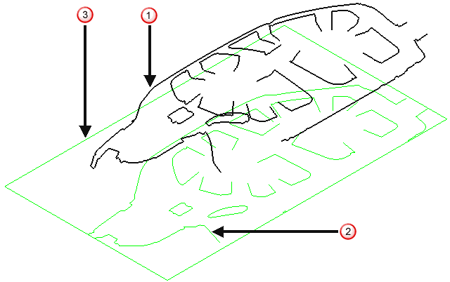
Axial offset — Enter an offset value. PowerMill uses this value to offset the lowest position of the toolpath along the tool axis from the position defined in Base position.
Pattern
Toolpath with an
Axial Offset of 0
Toolpath with an
Axial Offset of 20
 Axial Offset
Gouge check — Select this option so PowerMill checks the toolpath to see if any part of it gouges or deselect to turn gouge checking off.
Degouge tolerance — Enter the maximum distance, normal to the surface, that the toolpath can move to find a safe position. If gouges greater than this value are detected, then the tool is lifted axially to avoid the gouge.
Tolerance — Enter a value to determine how accurately the toolpath follows the contours of the model.
Cut direction — Select the milling technology.
Select a Cut Direction from the following:
-
Climb — Select to create toolpaths using only climb milling, where possible. The tool is on the left of the machined edge when viewed in the direction of tool travel.

-
Conventional — Select to create toolpaths using only conventional or upcut milling, where possible. The tool is on the right of the machined edge when viewed in the direction of tool travel.

- Any — Select to create toolpaths using both conventional and climb milling. This minimises the tool lifts and tool travel.
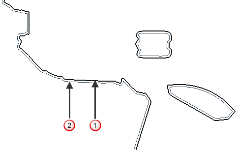
Curve thickness — Enter the offset of the curve.
the curve
toolpath with a
Thickness of
0
toolpath with a
Thickness of
20
Thickness
Preview — Click to produce a quick preview toolpath over the projection shape.
the curve
the preview toolpath
Draw — Select to display the preview pattern.