Create and import clamps, associate them with a setup, assign a single clearance for all clamps in the setup, and toggle the display of clamps in the graphics window.
To create a clamp
Click Model tab > Levels, Sets and Clamps panel > Create Clamp to create an empty clamp entity. Use the options in the Levels, Sets and Clamps panel to add model surfaces to the clamp.
To associate clamps with a setup
Associate clamps with a setup to let toolpaths in a setup automatically avoid or ignore the clamp surfaces.
- Click Setup tab > Edit panel > Settings.
- On the Setup dialog, select Clamps from the list view to display the Clamps page.
- Use the table to choose the clamps you want to associate with the setup.
- Click Close.
To specify the clearance of clamps in a setup
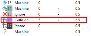
The specified clearance is associated with all the clamps in a setup. The clamp clearance is appended to the model thickness when toolpaths in the setup are calculated.
- Click Setup tab > Edit panel > Settings.
- On the Setup dialog, select Clamps from the list view to display the Clamps page.
- Enter the Clearance.
- Click Close.
The specified clearance is represented in the Component Thickness dialog by the Thickness of Set 16

To import model-surfaces as a clamp
- Click Setup tab > Edit panel > Settings.
- On the Setup dialog, select Clamps from the list view to display the Clamps page.
- Click
 to display the Import Clamp Model dialog.
- Locate and select the model, then click Open.
- Click Close.
To show or hide clamps
When a setup is activated, the associated clamps are displayed in the graphics window. Clamps that are not associated with the active setup are automatically hidden.
- Draw clamps to display the clamps associated with the active setup.
- Undraw clamps to hide the clamps associated with the active setup.