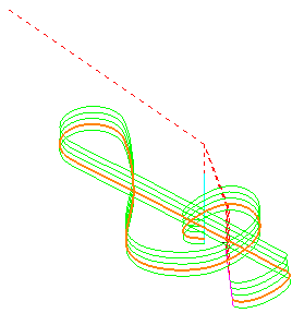
When you have an Embedded pattern you can use it to define the tool contact point of a toolpath. This example looks at an engraving toolpath. The Embedded Pattern Finishing dialog is similar to the Profile Finishing dialog.
- Click Home tab > Create Toolpaths panel > Toolpaths to display the Strategy Selector dialog.
- From the Finishing category, select Embedded Pattern Finishing.
- On the Tool page, select
 from the Tool list. This displays the Tapered Spherical Tool page.
 - On the Tapered Spherical Tool page:
- Enter a Diameter of 3.
- Enter a Tip Radius of 0.2.
- Enter a Taper Angle of 30.
- Enter a Length of 15.
- On the Tool axis page:
- Select a Tool Axis of Lead/Lean.
- Enter a Lead of 0.
- Enter a Lean of 0.
- Select a Mode of Contact Normal.
- On the Embedded pattern finishing page:
- In the Drive Curve frame, select an Embedded Pattern of TrebleClef_1 (created in Creating an embedded pattern example).
- In the Lower Limit frame, select an Axial Offset of -1.
- In the Gouge Avoidance frame, deselect Gouge Check. Because you are engraving the surface, you want the toolpath to gouge the surface.
- On the Multiple Cuts page:
- Select a Mode of Offset Down.
- Select an Order by of Level.
- Deselect Maximum Number of Cuts.
- Select Upper Limit and enter a value of 3. This option is only available when you select the Mode of Offset Down.
- Enter a Maximum Stepdown of 1.
- Click Calculate to create the embedded toolpath.

Note: You can see that the lowest pass of the toolpath is 1 mm below the embedded pattern. You get a difference between the toolpath and the embedded pattern as the embedded pattern is at the tool contact position and the toolpath is at the tool tip position.