Solids can be created by extruding single or multiple wireframe or text objects.
Extruded solids are edited in the same way as primitive solids.
If you intend to cut extruded solids into another solid, we recommend you use the Cut command instead of extruded solid. Similarly, if you intend to create a boss by adding an extruded solid to an existing solid, we recommend you use the Boss command.
To create an extruded solid:
- Select the wireframe or text objects you want to extrude.
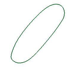
The example below shows a composite curve:

- Click Solid tab > Create panel > Extrusion.
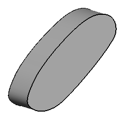
If a single wireframe or text object is selected, it is extruded to form a solid:

This is similar to creating an extruded surface, except caps are added to the solid if the wireframe object is planar and closed.
The solid is displayed in the solid feature tree. If there is no active solid in your model, this solid becomes active. Otherwise it becomes an inactive solid.
If multiple wireframe or text objects were selected, the Extrusion Dimensions dialog is displayed. Use this dialog to set the dimensions of the extruded solids.

For example:
- Select the following wireframe objects:

- Input the following values for the extruded solids:
Direction 1 - Length — This is the length of the extrusion. The Length of the extrusion can be zero if the Direction 2 - Length has a value other than zero.
Draft Angle — This is the draft angle between the base curve of the extruded solids and the curve at the other end. The angle is measured from the axis normal to the principal plane or the plane of best fit of the curve.
Direction 2 - Length — The length of the extrusion below the active plane.
- Click
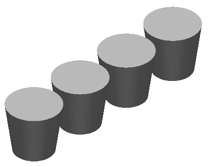
Preview to see the extruded solids:

You can change the Length and Draft Angle values and click Preview again to update the solids:

- Click OK to accept the preview and close the dialog.
- Select the following wireframe objects: