Nesting is the process of arranging parts in a sheet to minimise the required space and reduce the waste of raw materials. You can nest wireframe objects, meshes, surfaces, solids, components, electrodes, and workplanes. You can also nest text items and open wireframe curves when they are within the boundary of a valid object. Use the Nesting dialog to register objects as sheets and parts, and to arrange the parts for nesting in the sheet:
Sheets
Use the Sheets area of the dialog to select geometry and register it as the sheet to be used for nesting:
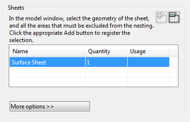
 Add as organised sheets — Click this button to register the selected geometry as a sheet for nesting and add it into the
Sheets
list. You can select multiple pieces of geometry simultaneously and add them as separate organised sheets. Each sheet can itself consist of multiple items whose relative positions are maintained.
 Remove sheet — Removes the selected sheet from the
Sheets list.
Name — Displays the name of the object added as a sheet.
Quantity — Displays the number of sheets. You can enter a value in this column to create copies of the sheet. If you create many parts, which cannot be arranged on one sheet, the excess parts are arranged on the copies of the sheet.
Usage — Displays the area, as a percentage, occupied by the parts nested on all the instances of the sheet.
As you move the mouse cursor over a sheet in the current model, the area usage for a particular sheet instance is shown below the Sheets list:
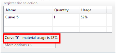
This is useful when you have several sheets on a model.
More options — If a sheet is selected, click this button to display additional nesting options for the selected sheet:
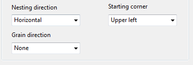
Nesting direction — Select the required nesting direction from the drop-down list.
Starting corner — Select the starting position for the nesting from the drop-down list.
Grain direction — Select the grain direction from the drop-down list.
Parts
Use the Parts area of the dialog to register items as parts and control how they are nested on the sheet:
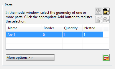
 Add as a single part — Click this button to add the selected geometry to the
Parts
list as a single part. You can use this button to register multiple pieces of geometry as a single part.
 Add as separate parts — Click this button to add the selected geometry to the
Parts
list as multiple separate parts. You can use this button to simultaneously register several pieces of geometry as separate parts.
Open curves and text items cannot be added as separate parts, as they must be contained within a valid boundary. An error message appears if you attempt to include open curves or text items in this type of nesting procedure:
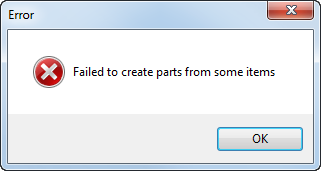
Click OK to continue with the nesting procedure, ignoring the incompatible items.
 Add as organised parts — Click this button to add multiple selected pieces of geometry to the
Parts list as multiple organised parts. Each part can itself consist of multiple items whose relative positions are maintained.
 Remove part — Remove the selected part from the
Parts
list.
Name — This column displays the name of the object added as a part.
Border — Enter a value into this column to specify the clearance around a part.
Quantity — Enter a value into this column to specify the number of copies of the part to nest.
Nested — In this column, PowerShape indicates the number of parts that were nested when the last nesting operation was applied.
 Choose boundaries — When an item has multiple boundaries, click this button to select:
- the boundary used as the outline of the part for nesting purposes.
- boundaries that are transformed along with the part.
More options — If a part is selected in the list, click this button to display additional options for the selected part:
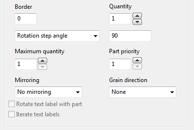
Border — As above.
Quantity — This is the minimum number of items of this type that PowerShape will attempt to nest on the sheets. When this number of items has been nested, PowerShape will attempt to nest more items up to the entered Maximum quantity. You can enter a value into this column or use the arrows to set the value.
Part rotation — Select the part rotation method from the drop-down list.
Rotation angle — Enter a part rotation step angle, or a list of angles separated by spaces.
Maximum quantity — Enter the maximum number of that part that can be nested. You can enter a value into this column or use the arrows to set the value.
Part priority — Enter the priority of the part. Use a priority of 1 to indicate that the part has the highest priority. You can enter a value into this column or use the arrows to set the value.
Mirroring — Select an option from the drop-down list to specify if the part can be mirrored and, if so, the mirroring method to be used.
Grain direction — Select the grain direction of the part from the drop-down list.
Rotate text label with part — When you duplicate parts, PowerShape rotates the parts to fit them in the sheet. Select this option to also rotate any text labels contained within the rotated parts.
Iterate text labels — When you duplicate parts that contain text items, select this option to produce a unique label for each copy. For example, if the part has a text item which contains the string 'A1', the text in the copies will contain 'A2', 'A3' and so on. This is useful as each nested item is easily identifiable.
For an example of the basic nesting procedure, see the An example of a nesting procedure topic.
General options
Use the General options area of the dialog to specify the general parameters that are to be used when nesting the parts:

Part distance — Use these buttons to select how the distance between the parts is to be calculated:
-
 Border to border — Click this button to calculate the distance between adjacent parts as the sum of the part borders.
-
 Border to clearance — Click this button to calculate the distance between adjacent parts as the sum of the part borders and the border clearance.
-
 Overlapping — Click this button to calculate the distance between adjacent parts as the largest part border.
 Create copies — Toggle this button to specify if a copy of the original sheets and part geometry should be created.
 Nesting boundaries — Toggle button to specify if the nesting boundaries of the sheets and parts should be created.
More options — Click this button to display additional general options:
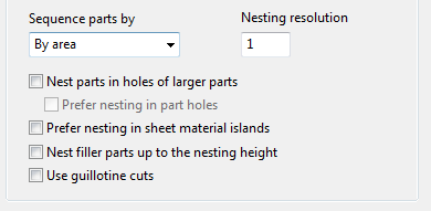
Sequence parts by — Select an option from the drop-down list to specify the order in which parts with the same priority are ordered for nesting:
- By area — Nest parts with the biggest area first.
- By perimeter — Nest parts with the biggest perimeter first.
Nesting resolution — Enter a value to specify the accuracy of the nested pattern. The actual distance between the parts can be greater than the specified value, by one resolution unit. The smaller the resolution, the higher the accuracy of the nesting, but the slower it is to calculate the layout.
Nest parts in holes of larger parts — If this option is selected, parts can be nested in the holes within larger parts.
Prefer nesting in part holes — If some of the nested parts have holes and this option is selected, PowerShape attempts to nest parts in the holes of the previously nested parts. If it isn't possible, the parts are nested elsewhere on the sheet.
Prefer nesting in sheet material islands — If the sheet material includes some islands and this option is selected, PowerShape attempts to nest parts in the holes of the sheet material islands. If it isn't possible, parts are nested elsewhere on the sheet.
Nest filler parts up to the nesting height — A filler is a part that is included in any space after the other parts have been nested in priority order. You define a filler part by setting a maximum number of parts.
- Deselect this option (default) to nest the minimum number of main parts, and include filler parts as required.
- Select this option to nest the minimum number of main parts, and include filler parts only up to the nesting height that is determined by the nesting of the main parts.
Use guillotine cuts — Select this option to align nested parts orthogonally so that a guillotine cut can be used to cut across the sheet (in either direction), without intersecting the nested parts.
Apply — Click this button to apply changes without closing the dialog.
Cancel — Click this button to cancel unapplied changes and close the dialog.