Use the Draft Faces dialog to change the draft angle of faces of a solid.
- Click Solid Tools tab > Modify Face panel > Draft to display the Draft Faces dialog.
- Select the Select the faces to draft option, and select the faces to draft.
- Select one of the following types of reference entity from the drop-down list:
- Face — a face of the solid.
- Surface — a surface of the model.
- Workplane — a workplane in the model.
- Select the Select the reference entity option, and select the reference entity.
- Use
 to define the draw direction.
- If this button is selected and the reference entity is a planar face or surface, the draw direction is defined as the normal of that face or surface. If the reference entity is a workplane, the draw direction is defined as the Z-axis of that workplane.
- If this button is not selected (or the reference entity face or surface is not planar), the draw direction is defined as the current principal plane axis.
- Enter an
Angle or use the drag handle to create the required draft angle.
Note: If you enter an angle that will make the draft face conflict with other geometry, the cursor changes to
 when it is moved over the model.
- Click
 to display the
Draft Faces Options dialog. Use this dialog to specify the way the graphics are previewed.
to display the
Draft Faces Options dialog. Use this dialog to specify the way the graphics are previewed.
- When more than solution is possible, use the
Previous and
Next Solution buttons to select the required solution.
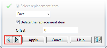
These buttons work on the current operation; when you have selected Apply, you are not able to change the solution for the applied operation.
- Click Apply to make the changes to the model.
Tip: When the
Draft Faces dialog is displayed, you can use Home tab > Selection panel > Restore to restore the previous set of selected faces to draft.