A schedule from assembly holes is a table containing details of the holes in the assembly.
To create the schedule, the assembly must be in an Active drawing view.
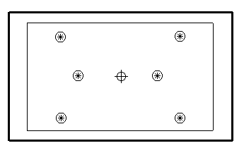
The model below is part of an assembly in an Active view. It is the view of an ejector plate in a mold base:
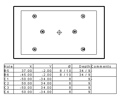
The following schedule is created for the holes in the ejector plate:
If the default Holes To Include setting is selected on the Schedule page of the Options dialog, only holes that are normal to the view are included in the schedule.
Only the holes of the selected components are included in the schedule. If none are selected, the holes of all the components are included.
Each hole is given a label in the view. All holes with the same size diameter start with the same letter and have the same Comment column.
If holes lie in the same line and have the same diameter, they are given the same label.
Through holes are now marked with an asterisk * in the schedule.
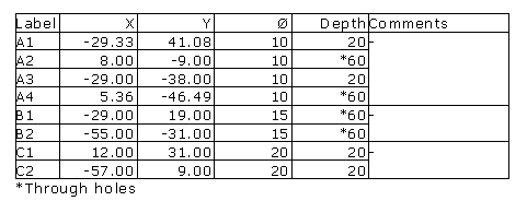
The schedule displays the labels, centres, diameters and depth of the holes. If a hole is tapered, it has two diameters.
You can specify further options on the Schedule page of the Options dialog.